Circuit : Ron J
Description:
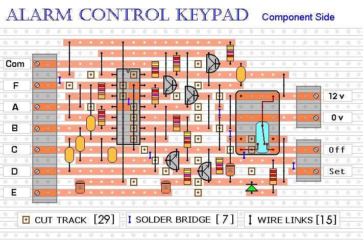
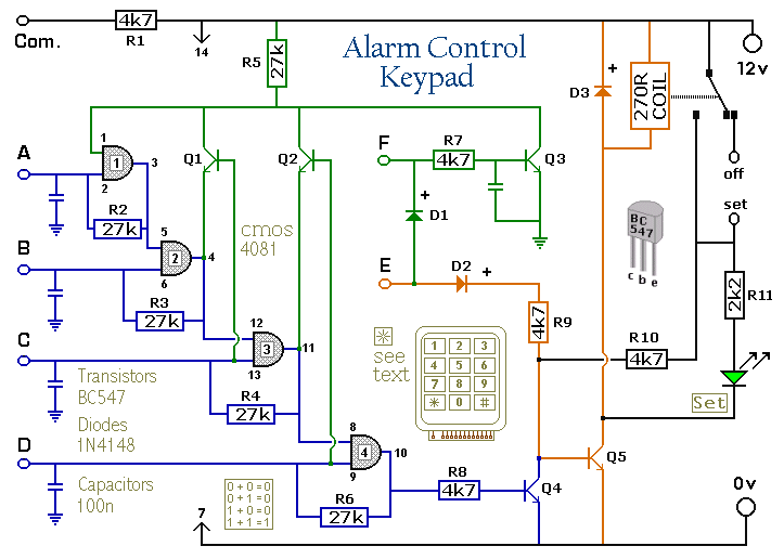
This is an enhanced 5 digit keypad which may be used with the Modular Alarm System.
Notes:
The Keypad must be the kind with a common terminal and a separate connection for each key. On a 12-key pad, look for 13 terminals. The matrix type with 7 terminals will NOT do. The Alarm is set by pressing a single key. Choose the key you want to use and wire it to 'E'. Choose the four keys you want to use to switch the alarm off, and connect them to 'A B C & D'. Your code can include the non-numeric symbols. With a 12-key pad, over 10 000 different codes are available. Wire the common to R1 and all the remaining keys to 'F'. When 'E' is pressed, current through D2 and R9 switches Q5 on. The relay energises, and then holds itself on by providing base current for Q5 through R10. The 12-volt output is switched from the "off " to the "set " terminal, and the LED lights. To switch the Alarm off again it is necessary to press A, B, C & D in the right order. The IC is a quad 2-input AND gate, a Cmos 4081. These gates only produce a high output when both inputs are high. Pin 1 is held high by R5. This 'enables' gate 1, so that when 'A' is pressed, the output at pin 3 will go high. This output does two jobs. It locks itself high using R2 and it enables gate 2 by taking pin 5 high. The remaining gates operate in the same way, each locking itself on through a resistor and enabling its successor. If the correct code is entered, pin 10 will switch Q4 on and so connect the base of Q5 to ground. This causes Q5 to switch off and the relay to drop out. Any keys not wired to 'A B C D or E' are connected to the base of Q3 by R7. Whenever one of these 'wrong' keys is pressed, Q3 takes pin 1 low. This removes the 'enable' from gate 1, and the code entry process fails. If 'C' or 'D' is pressed out of sequence, Q1 or Q2 will also take pin 1 low, with the same result. You can change the code by altering the keypad connections. If you need a more secure code use a bigger keypad with more 'wrong' keys wired to 'F'. A 16-key pad gives over 40 000 different codes. All components are shown lying flat on the board; but some are actually mounted upright. The links are bare copper wires on the component side. Two of the links must be fitted before the IC.
Veroboard Layout
The Support Material for this circuit includes a step-by-step guide to the construction of the circuit-board, a parts list, a detailed circuit description and more.
Friday, January 8, 2010
Tuesday, January 5, 2010
100W RMS Amplifier
100W RMS Amplifier
From: warren@eggo.csee.usf.edu
These materials are provided as-is, with no support. They are not being maintained. At present they are being kept available because we're aware people still refer to them - but we reserve the right to remove this archive, without notice, at any time.
Circuit Description: This is a 100 watt basic power amp that was designed to be (relatively) easy to build at a reasonable cost. It has better performance (read: musical quality) than the standard STK module amps that are used in practically every mass market stereo receiver manufactured today. When I originally built this thing, it was because I needed a 100 WPC amp and didn't want to spend any money. So I designed around parts I had in the shop.
The design is pretty much a standard one, and I'm sure there are commercial units out there that are similar. To my knowlwdge, it is not an exact copy of any commercial unit, nor am I aware of any patents on the topology. To experienced builders: I realize that many improvements and refinements can be made, but the idea was to keep it simple, and should be do-able by anyone who can make a circuit board and has the patience not to do a sloppy job.
The input stage is an LF351 op amp which provides most of the open loop gain as well as stabilizes the quiescent dc voltage. This feeds a level shift stage which references the voltage swing to the (-) rail. The transconductance stage is a darlington, to improve high-frerqency linearity. The 2SC2344 by itself has a rather large collector-base capacitance which is voltage dependent. The MPSA42 presents this with a low-z and has a C(ob) of only a few pf that is effectively swamped by the 33pF pole-splitting cap. The stage is supplied by the 2SA1011 active load (current source) which is about 20 ma. The current to the stage is limited by the 2N3094 to about 70 ma under worst case.
The output is a full complementary darlington with paralleled outputs. Although you could "get away with" only one if only 8 ohm easy-to-drive loads are used, this is not recommended. The use of parallel devices increases the ability to drive reactive loads (which can pull a significant current while the voltage waveform crosses zero and puts a high voltage and a high curent across the transistor simultaneously), gives the amp a higher damping factor, and reduces the maximum current each transistor has to supply to peaks (remember, the gain of a power transistor drops as the current increases).
Compensation is two-pole and one zero. The op-amp's pole and the pole generated by the 33pf cap and the 470 ohm bias resistor of the MPSA42 dominate. (the 33pF gets multiplied by the stage gain.) The 22 pf feedback capacitor provides lead compensation, and is taken from the output of the tranconductance stage rather than the output itself. In this way, the phase lag introduced by the output transistors is not seen by the high-frequency feedback. This intorduces a closed-loop pole which limits the high-frequency response. The two compensation capacitors must be type 1 creamic (NPO) or silver mica - with ZERO voltage coefficient.
The amp was designed to run 2 channels off a +/- 55 volt unregulated supply, reducing to +/- 48 volts under full load. It used a 40-0-40 volt, 5 amp toroid transformer, a bridge rectifier, and 10,000 uf of filter cap per side. If a standard EI transformer is used, a 6-amp rated unit should be used. With this power supply, it produces 100 watts continuous, both channels driven into 8 ohms resistive with no clipping. Dynamic headroom is about a db and a half. For more headroom, unloaded voltages to +/- 62 volts can be used with no circuit modification.
By the way, the schematic is in Postscript.
Limitations:
With no modifications the amp will drive 4-ohm speaker systems with no current limiting. The short-circuit current limit is set to about 4.5 amps peak, which will handle conventional speaker loads.(It will, of course, produce higher peak currents as the output voltage swing approaches the rail.) If you are going to be running some of those high-end speakers with impedance minima of half an ohm, or that stay reactive throughout most of the audio band ( ie, 0.5 +j3.2 ohms) you will probably already own a better amp than this. If the higher-power Motorola power transistors are used, it will drive a 2-ohm resistive load without problems (except heat).
I have never heard any slew-induced distortion on this amp with a CD player's band-limited (22KHz) signal. I suppose that real high-end freaks could pick it to pieces by hitting it with a TTL square wave mixed with a 19KHz stereo pilot tone and crank it up. I guarantee that there will be spurs all over the spectrum, but who listens to that?
Possible Modifications: (What if I want mo' power???) The Toshiba output transistors (2SD424/2SB554 pair) shoud not be used with supply voltages above +/-60 volts. If you plan on cranking it up, use more in parallel or use the 250 watt Motorola pairs (MJ15024/MJ15025). If very low impedances are expected, raise the bias in the transconductance stage to give more base drive to the output darlingtons or add another current gain stage. Higher-Beta (and faster) power transistors can't handle reactive loads worth a crap. Don't substitute high-fT parts unless you are sure they have adequate second-breakdown capability.
The NE5532 op-amp can be used in the input stage. If more than one are used off the +/-15 volt shunt regulators (balanced ins, anti-slew Bessel filters, etc.) the 2.7K dropping resistors may need to be reduced to say, 1.8K ohm to maintain regulation. The 2.7K resistors will allow up to 4 LF351 type op amps off the regulator (I used a quad 347 for balanced inputs to avoid hum in a DJ setup).
Construction tips: The output transistors and thermal compensator (2SC1567) will need to be mounted on a common heat sink - a finned unit measuring 5 in. high by 8 in. wide with 1.25 in fins should do nicely for one channel. (They look nice if you make the sides of the case out of them). Most normal applications won't require more cooling than this. The reason the 2SC1567 was chosen for the output bias regulator is because it is fully insulated - the ECG version will require additional mounting hardware. TO-3 hardware for the outputs is cheap and easy to get.
The driver transistors and voltage amps (2SC3344/2SA1011 pairs) will all require heatsinking as well. Individual TO-220 heat sinks on the circuit board will suffice - the voltage amps dissipate about 1.4 watts each. A common piece of 1/8 in. thick 1 in. wide X 4in. long angle aluminum will suffice for all 4 on each channel, but bear in mind that it must be oriented to take advantage of natural convection, and the transistors must be insualted.
Keep the imput grounds separate from everything else, and return them at ONE point. Failure to do so WILL result in high distortion (5% or so), or even oscillation.
The output stage bias should be set to about 25 milliamps in the output transistors. This value takes a while to stabilize, and you may have to monitor it over an hour or so during initial setup. To measure it, measure the voltage across the emitter resistor and use Ohm's law. This way, you can check the current sharing in the parallel output transistors at the same time and change them if there is a serious discrepancy. With parts of the same date code, they should not be off by more than 10% after it has warmed up. Higher output stage biases can be used, but it takes more care in setting it. If you want an idle current of more than 50 milliamps per side, increase the value of the emitter resistors.
Initial Checkout: DO NOT just plug something like this in! A seemingly insignificant error can set your house on fire! (As well as blow out $30 worth of transistors in a microsecond.) A variac will work in theory, but the amp may latch to the rail if the supply drops too low. I suggest the use of a ballast resistor - a 60 to 100 watt light bulb in series with the AC mains. You get a bright flash when the caps charge, and then it goes (almost) out as the idling supply current reaches its nominal low value. The amplifier will then work normally at low volumes. If the amp draws too much current for whatever reason, the lightbulb will glow brightly, increase resistance, and limit the power to the circuit. Usually, there will either be a mis-wire (use your DMM) or oscillation (will show up on a scope or RF power measuring device). If the bulb goes dim-bright-dim-bright... then the amp is marginally stable and the grounding layout should be checked. Compensation capacitor values may need to be adjusted if any significant changes were made. Mine is stable the way it is.
Additional Notes: The schematic is in postcript, so it should just be able to be printed out. The emitters of the transistors are labelled by an "e". I was too lazy to put arrows on the transistor symbols - and I've been using it that way for over a year now.
Trouble finding parts? MCM (1-800-543-4330) has all the transistors. Total cost for a stereo version should be between $150 and $250, depending on what kind of bargains you can find on the case, transformer, and heatsinks. If you have to pay "list" for everything, it will likely cost about $1000 to build.
The information included herin is provided as-is, with no warranties express or implied. No resposibility on the part of the author is assumed for the technical accuracy of the information given herein or the use or mis-use of said information.
The equipment described in this article was designed, fabricated, and tested on my own personal time using my own personal resources.
Click HERE to get the postscript circuit diagram.
100W Guitar Amplifier Mk II
Rod Elliott (ESP)
New Version Created 27 Jan 2002
Updated 11 Jan 2008
Rod Elliott (ESP)
New Version Created 27 Jan 2002
Updated 11 Jan 2008
Please Note: PCBs are available for for both power amp and preamp. Click the image for details.
Introduction Guitar amplifiers are always an interesting challenge. The tone controls, gain and overload characteristics are very individual, and the ideal combination varies from one guitarist to the next, and from one guitar to the next. There is no amp that satisfies everyone's requirements, and this offering is not expected to be an exception. The preamp is now at Revision-A, and although the complete schematic of the new version is not shown below, the fundamental characteristics are not changed - it still has the same tone control "stack" and other controls, but now has a second opamp to reduce output impedance and improve gain characteristics.
One major difference from any "store bought" amplifier is that if you build it yourself, you can modify things to suit your own needs. The ability to experiment is the key to this circuit, which is although presented in complete form, there is every expectation that builders will make modifications to suit themselves.
The amp is rated at 100W into a 4 Ohms load, as this is typical of a "combo" type amp with two 8 Ohm speakers in parallel. Alternatively, you can run the amp into a "quad" box (4 x 8 Ohm speakers in series parallel - see Figure 5 in Project 27b, the original article) and will get about 60 Watts. For the really adventurous, 2 quad boxes and the amp head will provide 100W, but will be much louder than the twin. This is a common combination for guitarists, but it does make it hard for the sound guy to bring everything else up to the same level.
Note: This is a fully revised version of the original 100W guitar amp, and although there are a great many similarities, there are some substantial differences - so much so that a new version was warranted. This is (in part) because PCBs are now available for both the power and preamps. The update was sufficiently substantial to warrant retaining the original version, which is still available as Project 27b.
Typical of the comments I get regularly about the P27 power and preamp combo is this e-mail from Tony ...
I'm delighted with the P27B/27 combination. It gives me the clear, punchy, uncluttered sound I've been looking for.This is just one of many, many e-mails I've received, but manages to sum up most of the comments in a couple of short sentences. This has been a popular project from the beginning, and is a solid and reliable performer that does not sacrifice sound or performance.
I've grown tired of whistles, bells and other embellishments that some anonymous guitar amp designer somewhere is telling me I've got to have. I've now got the sound I was hoping for. Love the Twin Reverb treble boost. Takes me back to 1960 !!
Without your module/boards and advice I'd have been playing about with breadboards for hours unsuccessfully searching for THE sound. Thanks.
When replacing guitar strings, never do so anywhere near an amplifier (especially a valve amp), nor close to a mains outlet. Because the strings are thin - the top "E" string in particular - they can easily work their way into mains outlets, ventilation slots and all manner of tiny crevices. The springiness of the strings means that they are not easily controlled until firmly attached at both ends. This is very real - click for an image of an Australian mains plug that was shorted out by a guitar string. |
The Pre-Amplifier A photo of the Revision-A preamp is shown below. You'll see that there are two dual opamps, but the schematic only shows one. This is the main part of the Rev-A update - the output section now has gain (which is easily selected), and a better buffered low output impedance. The remainder of the circuit is unchanged. Full details of the new version are available on the secure site for those who purchase the PCBs.
Guitar Pre-Amplifier Board (Revision A)
However, with a couple of simple changes, the preamp can be tamed to suit just about any style of playing. Likewise, the tone controls as shown have sufficient range to cover almost anything from an electrified violin to a bass guitar - The response can be limited if you wish (by experimenting with the tone control capacitor values), but I suggest that you try it "as is" before making any changes. (See below for more info.)
Figure 1 - Guitar Pre-Amplifier
Notes: 1 - IC pinouts are industry standard for dual opamps - pin 4 is -ve supply, and pin 8 is +ve supply. 2 - Opamp supply pins must be bypassed to earth with 100nF caps (preferably ceramic) as close as possible to the opamp itself. 3 - Diodes are 1N4148, 1N914 or similar. 4 - Pots should be linear for tone controls, and log for volume and master. |
The pin connections shown (either large dots or "port" symbols) are the pins from the PCB. Normally, all pots would be PCB types, and mounted directly to the board. For a DIY project, that would limit the layout to that imposed by the board, so all connections use wiring. It may look a bit hard, but is quite simple and looks fine when the unit is completed. Cable ties keep the wiring neat, and only a single connection to the GND point should be used (several are provided, so choose one that suits your layout. VCC is +35V from the main supply, and VEE is the -35V supply.
If you don't need all the gain that is available, simply increase the value of R6 (the first 4k7 resistor) - for even less noise and gain, increase R11 (the second 4k7) as well. For more gain, decrease R11 - I suggest a minimum of 2k2 here.
If the bright switch is too bright (too much treble), increase the 1k resistor (R5) to tame it down again. Reduce the value to get more bite. The tone control arrangement shown will give zero output if all controls are set to minimum - this is unlikely to be a common requirement in use, but be aware of it when testing.
The diode network at the output is designed to allow the preamp to generate a "soft" clipping characteristic when the volume is turned up. Because of the diode clipping, the power amp needs to have an input sensitivity of about 750mV for full output, otherwise it will not be possible to get full power even with the Master gain control at the maximum setting.
Make sure that the input connectors are isolated from the chassis. The earth isolation components in the power supply help to prevent hum (especially when the amp is connected to other mains powered equipment).
If problems are encountered with this circuit, then you have made a wiring mistake ... period. A golden rule here is to check the wiring, then keep on checking it until you find the error, since I can assure you that if it does not work properly there is at least one mistake, and probably more.
The input, effects and output connections are shown in Figure 1B.
- Input - these are quite the opposite of what you might think. The same basic idea is used on Fender amps, as well as nearly all others that have dual inputs for a channel. The Hi input is used for normal (relatively low output) guitar pickups, and is "Hi" gain. "Lo" in this design has about 14 dB less gain, and is intended for high output pickups so the first amplifier stage does not distort. The switching jack on the Hi input means that when a guitar is connected to the Lo input, it forms a voltage divider because the other input is shorted to earth.
- Effects - Preamp out and power amp in connections allow you to insert effects, such as compression (for really cool sustain, that keeps notes just hanging there), reverb, digital effects units, etc. The preamp out is wired so that the preamp signal can be extracted without disconnecting the power amp, so can be used as a direct feed to the mixer if desired. This is especially useful for bass. The preamp output can also be used to slave another power amplifier (as if you need even more - you do for bass, but not guitar).
- Output - A pair of output connectors is always handy, so that you can use two speaker boxes (don't go below 4 ohms though), or one can be used for a speaker level DI box. Because of the high impedance output stage, headphones cannot (and must not!) be connected to the speaker outputs. The 'phones will be damaged at the very least, but (and much, much worse) you could easily cause instant permanent hearing loss.
Figure 1B - Internal Wiring
You will see from the above diagram that I did not include the "loop breaker" circuit shown in the power supply diagram. For my needs, it is not required, for your needs, I shall let you decide. If you choose to use it, then the earth (chassis) connection marked * (next to the input connectors) must be left off.
A few important points ...
- The main zero volt point is the connection between the filter caps. This is the reference for all zero volt returns, including the 0.1 ohm speaker feedback resistor. Do not connect the feedback resistor directly to the amp's GND point, or you will create distortion and possible instability.
- The supply for the amp and preamp must be taken directly from the filter caps - the diagram above is literal - that means that you follow the path of the wiring as shown.
- Although mentioned above, you might well ask why the pots don't mount directly to the PCB to save wiring. Simple really. Had I done it that way, you would have to use the same type pots as I designed for, and the panel layout would have to be the same too, with exactly the same spacings. I figured that this would be too limiting, so wiring it is. The wiring actually doesn't take long and is quite simple to do, so is not a problem.
- I did not include the "Bright" switch in Figure 1B for clarity. I expect that it will cause few problems.
Bass Guitar, Electric Piano As shown, the preamp is just as usable for bass or electric piano as for rhythm or lead guitar. A couple of changes that you may consider are ...
- Delete the clipping diodes (unless fuzz bass/piano is something you want, of course). If these are removed, then the output should be taken directly from the Master output pin (M-OUT in Figure 1), so leave out / change the following ...
- Delete R14, and D1-D4
- Delete Q1 and associated components (C14, C15, R15, R16, R17)
- Delete VR5
- Change R13 from 4.7k to 100 ohms
Power Amplifier The power amp board has remained unchanged since it was first published in 2002. It certainly isn't broken, so there's no reason to fix it. The photo below shows a fully assembled board (available as shown as M27). Using TIP35/36C transistors, the output stage is deliberately massive overkill. This ensures reliability under the most arduous stage conditions. No amplifier can be made immune from everything, but this does come close.
Guitar Power Amplifier Board
Should the output be shorted, the constant current output characteristic will provide an initial level of protection, but is not completely foolproof. The short circuit protection will limit the output current to a relatively safe level, but a sustained short will cause the output transistors to fail if the amp is driven hard. The protection is designed not to operate under normal conditions, but will limit the peak output current to about 8.5 Amps. Under these conditions, the internal fuses (or the output transistors) will probably blow if the short is not detected in time.
Figure 2 - Power Amplifier
As shown, the power transistors will have an easy time driving any load down to 4 ohms. If you don't use the PCB (or are happy to mount power transistors off the board), you can use TO3 transistors for the output stage. MJ15003/4 transistors are very high power, and will run cooler because of the TO-3 casing (lower thermal resistance). Beware of counterfeits though! There are many other high power transistors that can be used, and the amp is quite tolerant of substitutes (as long as their ratings are at least equal to the devices shown). The PCB can accommodate Toshiba or Motorola 150W flat-pack power transistors with relative ease - if you wanted to go that way. TIP3055/2966 or MJE3055/2955 can also be used for light or ordinary duty. |
The speaker connections allow up to two 8 Ohm speaker cabinets (giving 4 Ohms). Do not use less than 4 ohm loads on this amplifier - it is not designed for it, and will not give reliable service!
All the low value (i.e. 0.1 and 0.22 ohm) resistors must be rated at 5W. The two 0.22 ohm resistors will get quite warm, so mount them away from other components. Needless to say, I recommend using the PCB, as this has been designed for optimum performance, and the amp gives a very good account of itself. So good in fact, that it can also be used as a hi-fi amp, and it sounds excellent. If you were to use the amp for hi-fi, the bias current should be increased to 50mA. Ideally, you would use better (faster / more linear) output transistors as well, but even with those specified the amp performs very well indeed. This is largely because they are run at relatively low power, and the severe non-linearity effects one would expect with only two transistors do not occur because of the parallel output stage.
Make sure that the bias transistor is attached to one of the drivers (the PCB is laid out to make this easy to do). A small quantity of heatsink compound and a cable tie will do the job well. The diodes are there to protect the amp from catastrophic failure should the bias servo be incorrectly wired (or set for maximum current). All diodes should be 1N4001 (or 1N400? - anything in the 1N400x range is fine). A heatsink is not needed for any of the driver transistors.
The life of a guitar amp is a hard one, and I suggest that you use the largest heatsink you can afford, since it is very common to have elevated temperatures on stage (mainly due to all the lighting), and this reduces the safety margin that normally applies for domestic equipment. The heatsink should be rated at 0.5° C/Watt to allow for worst case long term operation at up to 40°C (this is not uncommon on stage).
Make sure that the speaker connectors are isolated from the chassis, to keep the integrity of the earth isolation components in the power supply, and to ensure that the high impedance output is maintained.
Power Supply WARNING - Do not attempt construction of the power supply if you do not know how to wire mains equipment.
The power supply is again nice and simple, and does not even use traditional regulators for the preamp (details are on the preamp schematic in Figure 1). The power transformer should be a toroidal for best performance, but a convention tranny will do just fine if you cannot get the toroidal.
Do not use a higher voltage than shown - the amplifier is designed for a maximum loaded supply voltage of +/-35V, and this must not be exceeded. Normal tolerance for mains variations is +/-10%, and this is allowed for. The transformer must be rated for a nominal 25-0-25 volt output, and no more. Less is Ok if the full 100W is not needed. |
Figure 3 - Power Supply
Use good quality electrolytics (50V rating, preferably 105°C types), since they will also be subjected to the higher than normal temperatures of stage work. The bridge rectifier should be a 35 Amp chassis mount type (mounted on the chassis with thermal compound).
The earth isolation components are designed to prevent hum from interconnected equipment, and provide safety for the guitarist (did I just hear 3,000 drummers asking "Why ??"). The 10 Ohm resistor stops any earth loop problems (the major cause of hum), and the 100nF capacitor bypasses radio frequencies. The bridge rectifier should be rated at least 5A, and is designed to conduct fault currents. Should a major fault occur (such as the transformer breaking down between primary and secondary), the internal diodes will become short circuited (due to the overload). This type of fault is extremely rare, but it is better to be prepared than not.
Another alternative is to use a pair of high current diodes in parallel (but facing in opposite directions). This will work well, but will probably cost as much (or even more) than the bridge.
All fuses should be as specified - do not be tempted to use a higher rating (e.g. aluminium foil, a nail, or anything else that is not a fuse). Don't laugh, I have seen all of the above used in desperation. The result is that far more damage is done to the equipment than should have been the case, and there is always the added risk of electrocution, fire, or both.
Electrical Safety
Once mains wiring is completed, use heatshrink tubing to ensure that all connections are insulated. Exposed mains wiring is hazardous to your health, and can reduce life expectancy to a matter of a few seconds !
Also, make sure that the mains lead is securely fastened, in a manner acceptable to local regulations. Ensure that the earth lead is longer than the active and neutral, and has some slack. This guarantees that it will be the last lead to break should the mains lead become detached from its restraint. Better still, use an IEC mains connector and a standard IEC mains lead. These are available with integral filters, and in some cases a fuse as well. A detachable mains lead is always more convenient than a fixed type (until your "roadie" loses the lead, of course. You will never do such a thing yourself :-)
The mains earth connection should use a separate bolt (do not use a component mounting bolt or screw), and must be very secure. Use washers, a lock washer and two nuts (the second is a locknut) to stop vibration from loosening the connection.
Testing If you do not have a dual output bench power supply
Before power is first applied, temporarily install 22 Ohm 5W wirewound "safety" resistors in place of the fuses. Do not connect the load at this time! When power is applied, check that the DC voltage at the output is less than 1V, and measure each supply rail. They may be slightly different, but both should be no less than about 20V. If widely different from the above, check all transistors for heating - if any device is hot, turn off the power immediately, then correct the mistake.
If you do have a suitable bench supply
This is much easier! Do not connect a load at this time. Slowly advance the voltage until you have about +/-20V, watching the supply current. If current suddenly starts to climb rapidly, and voltage stops increasing then something is wrong, otherwise continue with testing. (Note: as the supply voltage is increased, the output voltage will fluctuate initially, then drop to near 0V at a supply voltage of about +/-15V or so. This is normal.)
Once all is well, connect a speaker load and signal source (still with the safety resistors installed), and check that suitable noises (such as music or tone) issue forth - keep the volume low, or the amp will distort badly with the resistors still there if you try to get too much power out of it.
If the amp has passed these tests, remove the safety resistors and re-install the fuses. Disconnect the speaker load, and turn the amp back on. Verify that the DC voltage at the speaker terminal does not exceed 100mV, and perform another "heat test" on all transistors and resistors.
When you are satisfied that all is well, set the bias current. Connect a multimeter between the collectors of Q10 and Q11 - you are measuring the voltage drop across the two 0.22 ohm resistors (R20 and R21). The desired quiescent current is 25mA, so the voltage you measure across the resistors should be set to 11mV +/-2mV. The setting is not overly critical, but at lower currents, there is less dissipation in the output transistors. Current is approximately 2.2mA / mV, so 10mV (for example) will be 22mA.
After the current is set, allow the amp to warm up, and readjust the bias when the temperature stabilises. This may need to be re-checked a couple of times, as the temperature and quiescent current are slightly interdependent. When you are happy with the bias setting, you may seal the trimpot with a dab of nail polish.
Note: If R22 gets hot or burns out, the amplifier is oscillating! This is invariably because of poor layout, inadequate (or no) shielding between preamp and power amp, or use of unshielded leads for the amplifier input. Please see the photos of my completed amp to see how it should be laid out. |
Please see Project 27B for the box designs and other useful info. Click here to see photos of the new amp
10 Watt Power Amplifier
10 Watt Power Amplifier |
|
| ||||||||||||||||||
Transistors: Tr1 BCY70 (or BC 182L or BC212L or BC214L) Tr2/3/4 BFY50/51 Tr5 BFX88 Tr6/7 2N3055 | ||||||||||||||||||
Risk of instability if no input connected. When testing, connect R (about 3k3). Needs well smoothed power supply of about 20 to 30 volts. Peak power is well over 10 Watts. | ||||||||||||||||||
The table below shows the approximate voltages to be expected when using a 24v supply and with the variable resistor set to give a current of about 40mA in the output stage. | ||||||||||||||||||
| ||||||||||||||||||
Circuit diagram : Component Side | ||||||||||||||||||
| ||||||||||||||||||
Circuit diagram : Copper Side | ||||||||||||||||||
|
Friday, January 1, 2010
60W Bass Amplifier
60W Bass Amplifier
Low-cut and Bass controls
Output power: 40W on 8 Ohm and 60W on 4 Ohm loads
Amplifier circuit diagram:
Amplifier parts:
R1__________________6K8 1W Resistor
R2,R4_____________470R 1/4W Resistors
R3__________________2K 1/2W Trimmer Cermet
R5,R6_______________4K7 1/2W Resistors
R7________________220R 1/2W Resistor
R8__________________2K2 1/2W Resistor
R9_________________50K 1/2W Trimmer Cermet
R10________________68K 1/4W Resistor
R11,R12______________R47 4W Wirewound Resistors
C1,C2,C4,C5________47µF 63V Electrolytic Capacitors
C3________________100µF 25V Electrolytic Capacitor
C6_________________33pF 63V Ceramic Capacitor
C7_______________1000µF 50V Electrolytic Capacitor
C8_______________2200µF 63V Electrolytic Capacitor (See Notes)
D1_________________LED Any type and color
D2________Diode bridge 200V 6A
Q1,Q2____________BD139 80V 1.5A NPN Transistors
Q3_____________MJ11016 120V 30A NPN Darlington Transistor (See Notes)
Q4_____________MJ11015 120V 30A PNP Darlington Transistor (See Notes)
SW1_______________SPST Mains switch
F1__________________4A Fuse with socket
T1________________220V Primary, 48-50V Secondary 75 to 150VA Mains transformer
PL1_______________Male Mains plug
SPKR______________One or more speakers wired in series or in parallel
Total resulting impedance: 8 or 4 Ohm
Minimum power handling: 75W
Preamplifier circuit diagram:
Preamplifier parts:
P1_________________10K Linear Potentiometer
P2_________________10K Log. Potentiometer
R1,R2______________68K 1/4W Resistors
R3________________680K 1/4W Resistor
R4________________220K 1/4W Resistor
R5_________________33K 1/4W Resistor
R6__________________2K2 1/4W Resistor
R7__________________5K6 1/4W Resistor
R8,R18____________330R 1/4W Resistors
R9_________________47K 1/4W Resistor
R10________________18K 1/4W Resistor
R11_________________4K7 1/4W Resistor
R12_________________1K 1/4W Resistor
R13_________________1K5 1/4W Resistor
R14,R15,R16_______100K 1/4W Resistors
R17________________10K 1/4W Resistor
C1,C4,C8,C9,C10____10µF 63V Electrolytic Capacitors
C2_________________47µF 63V Electrolytic Capacitor
C3_________________47pF 63V Ceramic Capacitor
C5________________220nF 63V Polyester Capacitor
C6________________470nF 63V Polyester Capacitor
C7________________100nF 63V Polyester Capacitor
C11_______________220µF 63V Electrolytic Capacitor
Q1,Q3____________BC546 65V 100mA NPN Transistors
Q2_______________BC556 65V 100mA PNP Transistor
J1,J2___________6.3mm. Mono Jack sockets
SW1_______________SPST Switch
Circuit description:
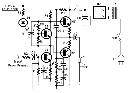
This design adopts a well established circuit topology for the power amplifier, using a single-rail supply of about 60V and capacitor-coupling for the speaker(s). The advantages for a guitar amplifier are the very simple circuitry, even for comparatively high power outputs, and a certain built-in degree of loudspeaker protection, due to capacitor C8, preventing the voltage supply to be conveyed into loudspeakers in case of output transistors' failure.
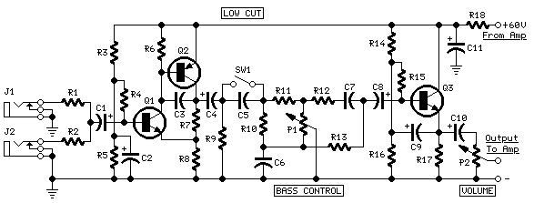
The preamp is powered by the same 60V rails as the power amplifier, allowing to implement a two-transistors gain-block capable of delivering about 20V RMS output. This provides a very high input overload capability.
Technical data:
- Sensitivity:
- 70mV input for 40W 8 Ohm output
- 63mV input for 60W 4 Ohm output
- Frequency response:
- 50Hz to 20KHz -0.5dB; -1.5dB @ 40Hz; -3.5dB @ 30Hz
- Total harmonic distortion @ 1KHz and 8 Ohm load:
- Below 0.1% up to 10W; 0.2% @ 30W
- Total harmonic distortion @ 10KHz and 8 Ohm load:
- Below 0.15% up to 10W; 0.3% @ 30W
- Total harmonic distortion @ 1KHz and 4 Ohm load:
- Below 0.18% up to 10W; 0.4% @ 60W
- Total harmonic distortion @ 10KHz and 4 Ohm load:
- Below 0.3% up to 10W; 0.6% @ 60W
- Bass control:
- Fully clockwise = +13.7dB @ 100Hz; -23dB @ 10KHz
- Center position = -4.5dB @ 100Hz
- Fully counterclockwise = -12.5dB @ 100Hz; +0.7dB @ 1KHz and 10KHz
- Low-cut switch:
- -1.5dB @ 300Hz; -2.5dB @ 200Hz; -4.4dB @ 100Hz; -10dB @ 50Hz
Notes:
-
The value listed for C8 is the minimum suggested value. A 3300µF capacitor or two 2200µF capacitors wired in parallel would be a better choice.
-
The Darlington transistor types listed could be too oversized for such a design. You can substitute them with MJ11014 (Q3) and MJ11013 (Q4) or TIP142 (Q3) and TIP147 (Q4).
-
T1 transformer can be also a 24 + 24V or 25 + 25V type (i.e. 48V or 50V center tapped). Obviously, the center-tap must be left unconnected.
-
SW1 switch inserts the Low-cut feature when open.
-
In all cases where Darlington transistors are used as the output devices it is essential that the sensing transistor (Q2) should be in as close thermal contact with the output transistors as possible. Therefore a TO126-case transistor type was chosen for easy bolting on the heatsink, very close to the output pair.
-
R9 must be trimmed in order to measure about half the voltage supply from the positive lead of C7 and ground. A better setting can be done using an oscilloscope, in order to obtain a symmetrical clipping of the output waveform at maximum output power.
-
To set quiescent current, remove temporarily the Fuse F1 and insert the probes of an Avo-meter in the two leads of the fuse holder.
-
Set the volume control to the minimum and Trimmer R3 to its minimum resistance.
-
Power-on the circuit and adjust R3 to read a current drawing of about 30 to 35mA.
-
Wait about 15 minutes, watch if the current is varying and readjust if necessary.
100W Audio Amplifier
|
How it Works
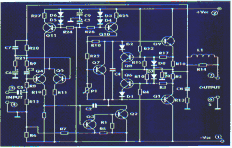
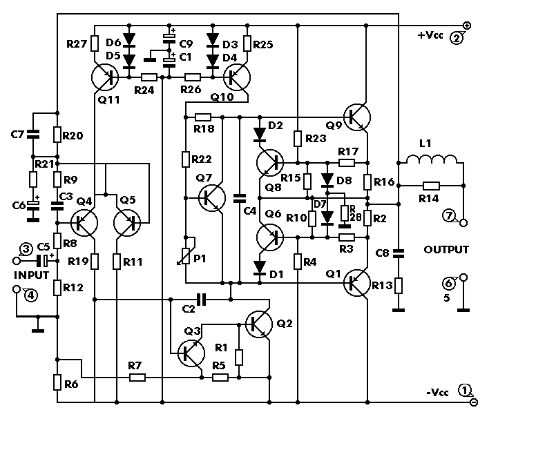
The circuit works from a symmetrical ñ40 VDC power supply and draws a maximum current of 2.6 A. The input circuit of the amplifier is a differential amplifier built around Q4 and Q5 that employ DC feedback thus preventing any DC voltage from appearing across the speaker with the usual destructive results. Q11 acts as a current source and ensures that the input stage draws a constant current of 1 mA. The signal which appears as a voltage drop across the resistor connected in series with the collector of Q4 is used to drive the DARLINGTON pair Q3, Q2 which together with the constant current source of 7 mA that is Q10, form the driver stage. This stage operates in class A and is driving the complementary output stage Q1, Q9. The transistor Q7 is used to balance the circuit at different temperatures and must be mounted on the heatsink between the out put transistors. The feedback loop which consists of R8, R9, C2, C3 provides AC stability to the circuit. The circuit also incorporates a protection stage that makes it virtually indestructible. This protection circuit is built around Q6, Q8. If for whatever reason the output remains connected on one supply rail and the common the output is also protected from high DC voltages that could burn the speakers. The supply rails should be protected by 2 A fuses for the 8 ohm version and 3 A for the 4 ohm.
Technical Specifications - Characteristics
Output power (f=1 KHz, d=0.5 %): 100 W in 8 ohm
Supply voltage: ................ ñ 40 V
Quiescent current: ............. 50 mA
Maximum current: ............... 2.6 A
Sensitivity: . 600 mV
Frequency response: ............ 10-35000 Hz (-1 dB)
Distortion HD: ................. 0.01 %
Intermodulation dist.: ......... 0.02 %
Signal/noise: 83 dBConstruction
PLEASE READ THIS BEFORE YOU START CONSTRUCTION
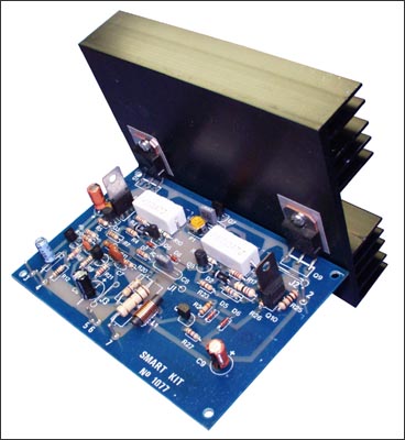
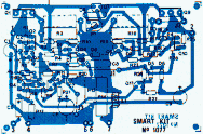
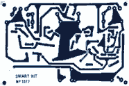
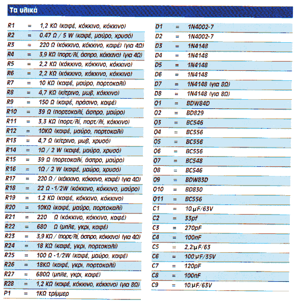
To cater for those who wish to use 4 ohm speakers with this amplifier the Kit includes the necessary components for both versions. The components that differ are R3,4,17 and 23. If you build the 8 ohm version then you must also include in the circuit R28 and D7, D8 which are not used in the 4 ohm version. As you see all the components are already marked on the component side of the p.c. board. The construction is made this way much simpler. Start the construction from the pins and the jumper connections, continue with the resistors and the capacitors and last solder in place the semiconductors. Check each resistor before soldering it, to see if
its colours match those in the component list. Be careful with the electrolytic capacitors because their polarity should be respected. The polarity of those capacitors is marked on their bodies and on the component side of the p.c. board.
NOTE: On the p.c. board next to R2, R16 are marked two other resistors which do not appear in the circuit diagram but are included in the components. They are of 1 ohm 2 W (brown, black, gold) and must be included in the circuit. Take care when you are soldering the semiconductors because if you overheat them they can be damaged. The output transistors should be mounted on the heatsink that is included in the kit. Take care not to short circuit them with the heatsink and we
recommend that you use some HTC between the transistor body and the sink in order to improve heat dissipation. Follow the diagram for the mounting of the power transistors as it shows clearly how to insert the insulators and the screws. Q7 should be made to touch the heatsink and is a good idea to use a bit of HTC between its casing and the surface of the heatsink. When you finish the construction of your project clean the board thoroughly with a solvent to remove all flux residues and make a careful visual inspection to make sure there are no mistakes, components missing and short circuits across adjacent tracks on the board. If everything is OK you can make the following connections: Input: 3 (signal), 5 (common) Output: 7 (signal), 6 (common) Supply: 1 (-40 VDC), 2 (+40 VDC) 5 (0 VDC)
Connect a milliammeter in series with the power supply, short the input of the amplifier, turn the power ON and adjust the trimmer P1 so that the quiescent current is about 50 mA. When you finish this adjustment remove the shunt from the input and connect the output of a preamplifier to it. Connect the pre amplifier to a suitable source and turn everything ON. The signal should be heard from the speakers clear and undistorted. First of all let us consider a few basics in building electronic circuits on a printed circuit board. The board is made of a thin insulating
material clad with a thin layer of conductive copper that is shaped in such a way as to form the necessary conductors between the various components of the circuit. The use of a properly designed printed circuit board is very desirable as it speeds construction up considerably and reduces the possibility of making errors. Smart Kit boards also come pre-drilled and with the outline of the components and their identification printed on the component side to make construction easier. To protect the board during storage from oxidation and assure it gets to you in perfect condition the copper is tinned during manufacturing and covered with a special varnish that protects it from getting oxidised and makes soldering easier. Soldering the components to the board is the only way to build your circuit and from the way you do it depends greatly your success or failure. This work is not very difficult and if you stick to a few rules you should have no problems. The soldering iron that you use must be light and its power should not exceed the 25 Watts. The tip should be fine and must be kept clean at all times. For this purpose come very handy specially made sponges that are kept wet and from time to time you can wipe the hot tip on them to remove all the residues that tend to accumulate on it. DO NOT file or sandpaper a dirty or worn out tip. If the tip cannot be cleaned, replace it. There are many different types of solder in the market and you should choose a good quality one that contains the necessary flux in its core, to assure a perfect joint every time.
DO NOT use soldering flux apart from that which is already included in your solder. Too much flux can cause many problems and is one of the main causes of circuit malfunction. If nevertheless you have to use extra flux, as it is the case when you have to tin copper wires, clean it very thoroughly after you finish your work. In order to solder a component correctly you should do the following:
- Clean the component leads with a small piece of emery paper. - Bend them at the correct distance from the component body and insert the component in its place on the board.
- You may find sometimes a component with heavier gauge leads than usual, that are too thick to enter in the holes of the p.c. board. In this case use a mini drill to enlarge the holes slightly. Do not make the holes too large as this is going to make soldering difficult afterwards.
- Take the hot iron and place its tip on the component lead while holding the end of the solder wire at the point where the lead emerges from the board. The iron tip must touch the lead slightly above the p.c. board.
- When the solder starts to melt and flow, wait till it covers evenly the area around the hole and the flux boils and gets out from underneath the solder. The whole operation should not take more than 5 seconds. Remove the iron and leave the solder to cool naturally without blowing on it or moving the component. If everything was done properly the surface of the joint must have a bright metallic finish and its edges should be smoothly ended on the component lead and the board track. If the solder looks dull, cracked, or has the shape of a blob then you have made a dry joint and you should remove the solder (with a pump, or a solder wick) and redo it.
- Take care not to overheat the tracks as it is very easy to lift them from the board and break them.
- When you are soldering a sensitive component it is good practice to hold the lead from the component side of the board with a pair of long-nose pliers to divert any heat that could possibly damage the component.
- Make sure that you do not use more solder than it is necessary as you are running the risk of short-circuiting adjacent tracks on the board, especially if they are very close together.
- When you finish your work cut off the excess of the component leads and clean the board thoroughly with a suitable solvent to remove all flux residues that still remain on it.
If it does not work
Check your work for possible dry joints, bridges across adjacent tracks or soldering flux residues that usually cause problems. Check again all the external connections to and from the circuit to see if there is a mistake there.
- See that there are no components missing or inserted in the wrong places.
- Make sure that all the polarised components have been soldered the right way round. - Make sure the supply has the correct voltage and is connected the right way round to your circuit.
- Check your project for faulty or damaged components. If everything checks and your project still fails to work, please contact your retailer and the Smart Kit Service will repair it for you.
or
L1 : 10 turns with wire 0,5mm turned on a restistor of 1W
If you use a 4Ohm speaker you will place R3,4,17,23 at the board.
If you use a 8Ohm speaker you will place D7 D8 and R28.
For R2 and R16 if you don't find a 0,47Ohm place two of 1 Ohm parallel.
R16 must be 0,47Ohm...the 1Ohm must be a typographical error, take care of this, i haven't tested it.
55W (Originally 75W) Power Amplifier
Hugh Dean / Rod Elliott (ESP)
Introduction This is a contributed project from Hugh Dean in Melbourne, Australia. Hugh has designed this amplifier for high quality and ease of construction.
Boards
To order boards, click to go to the ESP Purchase form. Verify the price and postage, then open the order form, fill it in and print it from your browser. Boards are sold only as a stereo pair, and are supplied with component overlay, circuit diagram, bill of materials and assembly and test instructions. These instructions are as an HTML file on floppy disk.
Kits
Complete kits for this amplifier are available now from the Printed Electronics web site. For those who do not want to have to scrounge all the component suppliers to get the parts, this is definitely the way to go. Details and all pricing are available from Printed Electronics - as these may change over time I shall not reproduce them here.
Please Note
According to the latest information on the Printed Electronics web site, the amp has been "downgraded" to 55W, which is still more than enough power for all but the most inefficient loudspeakers. The maximum recommended supply voltage is +/-35V, and it is recommended that this is not exceeded (the amp was previously stated to use a +/-42V supply voltage). The drawings below have been duly amended to reflect this change.
Description
From the designer, Hugh Dean ...
The AKSA is a highly refined push pull solid state stereo amplifier of 55W per channel.
It was developed to overcome most of the sonic problems of transistor amplifiers, and incorporates some highly innovative thinking from an experienced designer. It delivers stunning resolution and a pure, sweet sound at very low cost.
Both channels are assembled on their own individual 86mm x 75mm boards and mounted on a single 300 x 75 mm ledged heatsink. It is powered from a 35 volt positive and negative supply, and runs very efficiently in Class AB.
Features of this amplifier are its lack of intermodulation and depth of stereo image, unusual for a solid state amplifier. To achieve the best performance, a dual mono power supply is required - a schematic is supplied with the boards.
To cap it off, the boards are designed so that it can be built up to 100W per channel (into 4 ohms) with only minor changes to various components and the addition of an extra pair of output transistors on each channel.
The complete unit including the power supply can be built up in an afternoon in a suitable case.
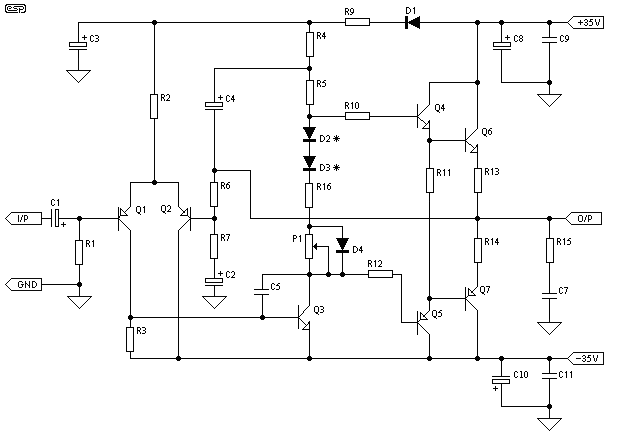
The circuit diagram for the amp is shown in Figure 1. As can be seen, it is not a complicated amplifier, and all components (excluding power supply) fit onto a single board.
Figure 1 - 75W Power Amplifier
A full schematic with all component values and assembly instructions is available with the circuit boards. Normally all ESP projects have complete schematics, but this is not my intellectual property and I will always protect the interests of my contributors.
* The pot (P1) is used to set quiescent current. This will normally be adjusted to 100mA. No bias servo is used - instead, the diodes D2 and D3 (1N4148 types) are mounted so that they are in contact with the main heatsink. These must have their leads insulated and be secured using Superglue to ensure good thermal contact.
All diodes are 1N4148 or 1N914. Q3 should have a small TO-220 heatsink to prevent overheating.
Apply power (preferably with 22 ohm safety resistors installed in series with the +ve and -ve supply lines) with the pot P1 at minimum resistance - do NOT connect a speaker at this time. Check for heating of any components, and ensure that the voltage at the output is less than 1 Volt.
To adjust the bias current, reinstall the fuses, do not connect a speaker and apply power. Wait for a few minutes for the amp to stabilise, then measure the voltage across one of the 0.47 ohm output emitter resistors. Carefully adjust P1 - when you read a voltage of 47mV, this equates to 100mA. Verify that the output voltage is within about 100mV. After a few minutes (checking for heat in the meantime), check the quiescent current again, and adjust as needed.
NOTE: Full schematic, bill of materials, assembly and test instructions are included with each printed circuit board order.
Power Supply
WARNING:Mains wiring must be performed by a qualified electrician - Do not attempt the power supply unless suitably qualified. Faulty mains wiring may result in death or serious injury. |
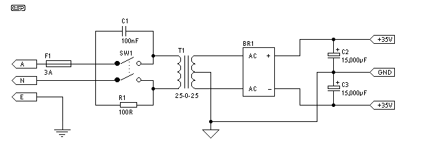
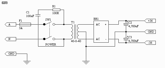
The amp can be operated as a stereo pair form a single supply as shown in Figure 2. Depending on your needs, this will often be quite adequate. Note the capacitor and resistor (R1 and C1) across the mains switch. The capacitor must be rated for at least the full AC supply voltage (i.e. 120V or 240V AC), and all wiring (including the 100 ohm resistor) should be well insulated to prevent accidental contact to the chassis or a finger. Please read the disclaimer for further suitable warnings about mains wiring.
Figure 2 - Single Power Supply
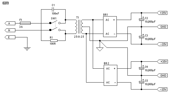
A better solution is to use a "dual-mono" supply. This shares one transformer, but uses two bridge rectifiers and two sets of filter capacitors. This arrangement minimises any interaction between the amps, and is shown in Figure 3. This supply is virtually identical to the one I presented as Project 04 except for the voltage. Two other differences will be seen if the two are compared - My original supply has an inbuilt "earth-loop breaker" circuit, and this one has an RC "snubber" circuit across the mains switch. Either of these can be applied on either power supply as required.
300W Subwoofer Power Amplifier
Rod Elliott (ESP)
Introduction High power amps are not too common as projects, since they are by their nature normally difficult to build, and are expensive. A small error during assembly means that you start again - this can get very costly. I recommend that you use the PCB for this amplifier, as it will save you much grief. This is not an amp for beginners working with Veroboard!
The amplifier can be assembled by a reasonably experienced hobbyist in about three hours. The metalwork will take somewhat longer, and this is especially true for the high continuous power variant. Even so, it is simple to build, compact, relatively inexpensive, and provides a level of performance that will satisfy most requirements.
WARNINGS:
- This amplifier is not trivial, despite its small size and apparent simplicity. The total DC is over 110V, and can kill you.
- The power dissipated is such that great care is needed with transistor mounting.
- The S300 is intended for intermittent duty on 4 Ohm loads, as will normally be found in a subwoofer. It is NOT intended for PA or any other continuous duty, and although it may work fine for may years, I absolutely do not recommend this.
- For continuous duty, do not use less than 8 Ohms.
- There is NO SHORT CIRCUIT PROTECTION. The amp is designed to be used within a subwoofer enclosure, so this has not been included. A short on the output will almost certainly destroy the amplifier.
DO NOT ATTEMPT THIS AMPLIFIER AS YOUR FIRST PROJECT
Description
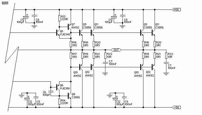
Please note that this amp is NOT designed for continuous high power into 4 Ohms. It is designed for intermittent duty, suitable for an equalised subwoofer system (for example using the ELF principle - see the Project Page for the info on this circuit). Where continuous high power is required, another 4 output transistors are needed, wired in the same way as Q9, Q10, Q11 and Q12, and using 0.1 ohm emitter resistors.
Continuous power into 8 ohms is typically over 150W, and it can be used in the form shown at full power into an 8 ohm load all day, every day. The additional transistors are only needed if you want to do the same thing into 4 ohms!
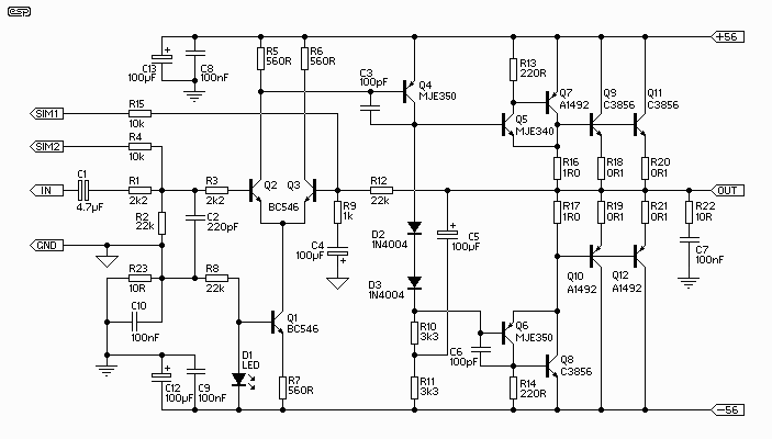
The circuit is shown in Figure 1, and it is a reasonably conventional design. Connections are provided for the Internal SIM (published elsewhere on the Project Pages), and filtering is provided for RF protection (R1, C2). The input is via a 4.7uF bipolar cap, as this provides lots of capacitance in a small size. Because of the impedance, little or no degradation of sound will be apparent. A polyester cap may be used if you prefer - 1uF with the nominal 22k input impedance will give a -3dB frequency of 7.2Hz, which is quite low enough for any sub.
Figure 1 - Basic Amplifier Schematic
The Class-A driver is again conventional, and uses a Miller stabilisation cap. This component should be either a 500V ceramic or a polystyrene device for best linearity. The collector load uses the bootstrap principle rather than an active current sink, as this is cheaper and very reliable (besides, I like the bootstrap principle :-)
All three driver transistors must be on a heatsink, and D2 and D3 should be in good thermal contact with the driver heatsink. Neglect to do this and the result will be thermal runaway, and the amp will fail. |
Although I have shown 2SC3856 and 2SA1492 output transistors, most constructors will find that these are not as easy to get as they should be. The alternatives are MJL21193 / MJL21194 or 2SC3281 / 2SA1302 respectively.
Use a standard green LED (do not use high brightness or other colours) - this may be a miniature type if desired. The resistors are all 1/4W (preferably metal film), except for R10, R11 and R22, which are 1W carbon film types. All low value resistors (1 ohm and 0.1 ohm) are 5W wirewound types.
Because this amp operates in "pure" Class-B (something of a contradiction of terms, I think), the high frequency distortion will be relatively high, and is unsuited to high power hi-fi. At the low frequency end of the spectrum, there is lots of negative feedback, and distortion is actually rather good, at about 0.04% up to 1kHz.
Power output into 4 ohms is over 250W continuous, and for transients exceeds 300W easily. Use of a big power transformer and massive filter caps will allow the amp to deliver close to 350W continuous, but if you really want to use it like that, I very strongly recommend the additional output transistors (see above comments on this topic).
Power Dissipation Considerations
I have made a lot of noise about not using this amp for continuous duty into 4 ohms without the extra transistors. A quick calculation reveals that at the worst case, the output and transistor voltage will be the same - i.e. at 28V. With 28V, load (and transistor) current is 7A, so the instantaneous dissipation is therefore 28 * 7 = 196W. This means that the four final transistors do most of the work, with the others having a relatively restful time.
Since I like to be conservative, I will assume that they contribute no more than about 1.5A (which is about right). This means that they only dissipate 48W, with the main O/P devices dissipating a peak of 74W each. The specified transistors are 130W, and the alternatives are 150W, so where is the problem?
The problem is simple - the rated dissipation for a transistor is with a case temperature of 25oC. As the amp is used, the case gets hot, and the standard derating curves should be applied. Add to this the reactive component as the loudspeaker drives current back into the amp, and it becomes all to easy to exceed the device dissipation limits.
Figure 1a - Double Output Stage
A Few Specs and Measurements
The following figures are all relative to an output power of 225W into 4 ohms, or 30V RMS at 1kHz, unless otherwise stated. Noise and distortion figures are unweighted, and are measured at full bandwidth. Measurements were taken using a 300VA transformer, with 6,800uF filter caps.
Mains voltage was about 4% low when I did the tests, so power output will normally be slightly higher than shown here if the mains are at the correct nominal voltage.
Gain | 27dB |
Power (Continuous) | 240W (4 ohms) |
153W (8 ohms) | |
Peak Power - 5 ms | 185W (8 ohms) |
Peak Power - 10 ms........ | 172W (8 ohms) |
Input Voltage | 1.3V |
Noise | -63dBV (ref. 1V) |
S/N Ratio | 92dB |
Distortion | 0.4% |
Distortion (@ 4W) | 0.04% (1 Khz) |
Distortion (@ 4W) | 0.07% (10 kHz) |
Slew Rate | > 3V/us |
Power Bandwidth | 30 kHz |
Note that the "peak power" ratings represent the maximum power before the filter caps discharge and the supply voltage collapses. I measured these at 5 milliseconds and 10 milliseconds. Performance into 4 ohm loads will not be quite as good, as the caps will discharge faster. The supply voltage with zero power measured exactly 56V, and collapsed to 50.7V at full power into 8 ohms, and 47.5V at full power into 4 ohms.
Power Supply
WARNING: Mains wiring must be performed by a qualified electrician - Do not attempt the power supply unless suitably qualified. Faulty or incorrect mains wiring may result in death or serious injury. |
The basic power supply is shown in Figure 2. It is completely conventional in all respects. Use a 40-0-40 V transformer, rated at 300VA for normal use. For maximum continuous power, a 500VA or bigger transformer will be needed. This will give a continuous power of about 350W, and peak power of close to 400W is possible with a good transformer. Remember my warnings about using the amp in this way, and the need for the additional output transistors.
Figure 2 - Basic Power Supply Circuit
C1 must be rated for 240V AC (or 120V AC) operation - do not use standard 250V DC caps under any circumstance, as they will fail, and R1 will explode! This is not intended as humour - this is fact! C1 and R1 may be omitted in most cases, and if you cannot get a mains rated capacitor I suggest that you don't install these components.
The supply voltage can be expected to be higher than that quoted at no load, and less at full load. This is entirely normal, and is due to the regulation of the transformer. In some cases, it will not be possible to obtain the rated power if the transformer is not adequately rated.
Bridge rectifiers should be 35A types, and filter capacitors must be rated at a minimum of 63V. Wiring needs to be heavy gauge, and the DC must be taken from the capacitors - not from the bridge rectifier.
Although shown with 4,700uF filter capacitors, larger ones may be used. Anything beyond 10,000uF is too expensive, and will not improve performance to any worthwhile degree. Probably the best is to use two 4,700uF caps per side (four in all). This will actually work better than a single 10,000uF device, and will be cheaper as well.
NOTE: It is essential that fuses are used for the power supply. While they will not stop the amp from failing (no fuse ever does), they will prevent catastrophic damage that would result from not protecting the circuit from over-current conditions. Fuses can be mounted in fuseholders or can be inline types. The latter are preferred, as the supply leads can be kept as short as possible. Access from outside the chassis is not needed - if the fuses blow, the amplifier is almost certainly damaged.
What Does It Look Like?
I have included a photo of the prototype amp, fully mounted on its heatsink. For normal use, some brackets would also be needed to mount the heatsink, unless two assemblies were used as the side panels of a conventional (stereo) amplifier chassis.
Figure 3 - Completed Amp Module
Alarms and security related schematics
- 4 Photo-Detector circuit with delayed release and bipolar output
- 5 Zone Alarm Circuit
- 5 Zone alarm circuit
- 5 Zone Alarm System
- Alarm control keypad
- Automatic Intruder Alarm
- Build an iButton electronic lock based around a AT91C2051 microcontroller (includes ASM source code)
- CMOS single zone intruder alarm
- Cold activated switch (frost alarm)
- Combination Lock (PIC16F84)
- Constructing your own Light Alarm
- Digital combination lock
- Digital combination lock using pair of CD4013 CMOS chips
- Digital Keypad Combination Lock
- Door Alarm circuit diagram
- Door knob alarm (PDF)
- Doorbell for the Deaf
- Easy to build tripwire activated alarm
- Electronic door codelock (PIC16F84)
- Electronic locker digital combination lock circuit diagram
- Emergency Light & Alarm
- Enhanced 4 Digit Alarm Keypad
- Enhanced 5 Digit Alarm Keypad
- Everything-that-moves alarm works by inducing eddy currents in living beings
- Fire alarm circuit diagram based on LDR (light-dependent resistor)
- Fridge door Alarm
- Frost alarm
- Gate alarm
- Gate alarm circuit
- Home security project
- iButton electronic lock (Dallas DS1990A)
- MC68HC908-based wireless monitoring system is adaptable for use in domestic and industrial settings
- Micro-power over temperature alarm (PDF)
- Miniature loop alarm
- Miniature Loop Alarm
- Modular Burglar Alarm
- Motorcycle alarm
- Multi-zone burglar alarm
- Novel Buzzer
- Perimeter monitor
- Proximity detector (uses human body capacitance)
- Proximity detector for humans / living creatures using eddy current detection
- Rain alarm / rain detector
- Refrigerator door alarm
- Refrigerator Door Alarm
- RF Alarm
- RF Pad - combination-controlled, fully customizable radio frequency remote control
- Single Zone Alarm
- Single Zone CMOS Alarm
- Smartcard controlled relay circuit based around Nutchip microcontroller
- Sun - Up Alarm
- Touch activated alarm system
- Transistor based single zone intruder alarm
- Travel Touch Alarm
- Ultrasonic radar alarm
- Ultrasonic Radar Alarm Circuit Diagram
- Ultrasonic remote control & alarm system
- Wailing alarm siren
- Water Activated Alarm
- Water level alarm
- Water Level Indicator with alarm
- Water seepage alarm (PDF)
- Waterpump Safety Guard for fish pond / fish tank
- Wire loop alarm
- Wire Loop Alarm using 4001UBE Quad NOR Gate
- Wireless alarm system based around Nutchip microcontroller
Audio power amplifier schematics
- 10 Watt Audio Amplifier
- 10 watt audio power amplifier using discrete transistors (includes PCB layout)
- 100W Guitar Amplifier
- 100W RMS Amplifier
- 13.5 Watt Power Amplifier using a TL081 opamp and TIP125 / TIP120 power transistors
- 150W audio amplifier that's cheap to build using TIP142 / TIP147 Darlington power transistors
- 16 Watt amplifier
- 20 Watt / Channel Stereo Power Amplifier
- 20 Watt Audio Power Amplifier
- 20 Watt Class-A Power Amplifier
- 22 Watt Audio Amplifier
- 22 Watt Stereo Amplifier using TDA1554
- 22W Audio Amplifier
- 25 Watt MOSFET Audio Amplifier using IRF532 / IRF9532 hexfet transistors for output stage
- 25W MOSFET audio amplifier
- 2W Audio Amplifier using BD139 and BD140 transistors
- 300W Subwoofer Power Amplifier
- 4 channel power amplifier with bi-amping and bridging options
- 4W amplifier
- 50 Watt Amplifier
- 50W Amplifier
- 50W audio amplifier using ICL8063
- 50W audio power amplifier
- 8 Watt amplifier
- 8 watt audio amp
- Ampliefied speaker, built for MP3 player but can be used with other headphone only devices (PDF)
- Amplified ear for surveillance
- Amplifier based on LM4780 including a thermal shutdown feature
- Audio Amp Output Power Limiter
- Audio amplifier output relay delay
- Audio amplifier with squelsh-control
- Build a good Audio Buffer Amplifier
- Class-A/AB Amplifier delivering 100W into a 4 ohm load
- Class-C power amplifier
- CMoy pocket headphone amplifier
- Compact 50W Integrated Amplifier with Meier Headphone Section
- Death of Zen (DoZ) - A New Class-A Power Amp
- DPA 220 amplifier schematic
- DPA 440 amplifier schematic
- DPA 880 amplifier schematic
- Easy to build DIY 50W amplifier based on ICL8063
- El-Cheapo - A Really Simple Power Amplifier
- Five Tube Stereo Amplifier
- Hammonator Organ to Guitar Amp Conversion (tube amplifier)
- HeadBanger Headphone Amp
- Headphone amplifier based on 12AX7 tubes
- Headphone monitor amp
- Headphone practice amplifier
- Hi-Fi Headphone Amplifier
- High quality exponential VCA
- LM380 2.5 watt audio amplifier circuit
- Low impedance microphone amplifier
- Low Power Audio Amp Experiments
- Low power audio amplifier using BC109C along with BD679 and BD680 Darlington pairs
- Mini bench amplifier (LM386)
- Miniature audio amplifier
- Mini-MosFet Audio Amplifier
- More Discrete BJT, Low Power AF Amp Experiments
- Potpourri of Transistor Audio Amplifier Circuits
- Quadraphonic Amplifier based on pair of LM1877 devices
- Ruby is an "enhanced" version of the Little Gem battery-powered amplifier (LM386 based design)
- Selection of Integrated Circuit Audio Amplifiers
- Simple class-D amplifier based on 555 pulse width modulator
- Single Chip 50 Watt / 8 Ohm Power Amplifier
- Small bench amplifier ideal for testing audio stages in circuits
- Soft-Start Circuit For Power Amps
- Spatial Distortion Reduction Headphone Amp
- Speech Amplifier Box
- Stereo audio amplifier based on TDA2822M
- Super linear Headphone amplifier
- TDA2030 8 Watt amplifier
- Thermo-Fan To Keep Your Amp Cool
- Tube amplifier
- Two 9v battery-powered amps based on the LM386. Schematic and PCB/perfboard layouts.
- Two Transistors Audio Amplifier
- Voice Amplifier
Audio preamp circuits
- Altec 1564A Preamp Power Supply
- Altec 428B Microphone Preamplifier schematic
- API 321 mic preamp schematic
- Audio preamp
- Audio preamplifier
- Balanced microphone preamp
- Basic low frequency preamplifier circuits
- Bat detector microphone pre-amplifiers
- ECM Mic preamp
- Electret mic amplifier
- FET Preamp Cable
- Hi Fi preamp
- Hi-Fi Preamp with remote-control and other advanced features
- High quality audio preamplifier (OPA2134)
- Intercom preamp
- Low impedance microphone amplifier
- Masthead preamp
- Microphone preamp for portable transceivers
- Microphone pre-amp with high emphasis
- Neumann U67 microphone preamp power supply
- RCA BA-1A two-stage preamp schematic
- RCA BA-21A preamplifier schematic
- RCA BA-31A preamplifier schematic
- Simple microphone preamplifier
- Simple transistor preamp - includes a PCB layout
- Sound card microphone preamplifier
- Ultra-Simple Guitar Preamp
- Vacuum Tube Microphone Preamp
- Voltage follower with 1G ohm input resistance based on LM11 opamp
Automotive, car and motorcycle schematics
- 12V battery level indicator for car batteries
- 12V to 9V car coverter
- 20 Segment Expanded Scale Voltmeter including a PCB design
- 3 Channel, 12 Volt Color Organ for a car
- 3rd brake light
- 5301 wideband fuel mixture display
- 80188XL Engine Tachometer / Race Computer
- Adaptive Windscreen Wiper Control
- Authentic Looking Knight Rider Led Project
- Automatic Headlight Brightness Switch
- Automatic headlight brightness switch
- BMW R Series Motorcycle Regulator Schematic
- Brakelight Flasher
- Breakdown safety beacon
- Car acceleration meter
- Car Alarm Arming Horn Beep Canceller
- Car backup / reversing alarm
- Car Battery Charger
- Car battery charger
- Car battery charger circuit
- Car Battery Charger, an SCR Design with a 10 Amp rating
- Car battery voltage tester using LM3914
- Car burglar alarm circuit
- Car Door Keypad Using LIN network
- Car Nicad charger
- Car OBD II J1850 PWM, J1850 VPW, ISO-9141 cables schematic pinout
- Car OBDII diagnostic interface cable schematic pinout
- Car power supply unit for digital projects, small car PCs etc
- Car Timer with Atmel ATiny45 to automatically turn of accessories to prevent flat battery
- Combination lock for car liftgate
- Common Ground for Older VPW OBD Circuit
- Custom USB tyre pressure monitoring system
- Economy radar detector
- Electronic car ignition circuit
- Engine control unit schematics
- FCD (Fuel Cut Defencer)
- Flashing / pulsing third brake like for cars
- Flashing light / emergency beacon for vehicle
- Fuel injector pulse width monitor
- Grand Cherokee Off-Highway Lights
- Headlight flasher
- Headlight guard
- Headlight reminder
- Headlight timer
- Hijack alarm
- Interface between GM's 5 Volt 8192 baud ALDL data stream and a PC serial port
- Interior light extender
- KITT (from Knight Rider) Car scanner using incandescant lamps
- Large capacitor charge "controllers" (Car Audio)
- Low battery cut-off circuit for a car or truck
- Motorctcle turning signal system
- Motorcycle battery charger
- Motorcycle brake light flasher
- Motorcycle low battery voltage warning circuit
- Opendiag OBD-II Schematics & PCB Layout Opendiag OBD-II Schematics & PCB Layout
- Parking aid senses distance to rear of vehicle
- Portable CD Player Adapter For Car
- Seatbelt reminder circuit
- Simple car battery charger
- Simple car battery voltage monitor
- Simple Car Preamplifier and Artificial Earth
- Simple Vehicle Loop Detector (inductive loop for driveway etc)
- Speed alert - wireless portable unit
- Synchronized multi-spark module (SMSM) for Electronic Ignition Devices (EID)
- Third brake light pulser circuit
- Two LED trouble light system
- Ultrasonic parking sonar electronic circuit diagram using transistors and 4000 series CMOS
- Wide Band Fuel Mixture Display
- Wiper Speed Control
- Wireless Auto Tachometer
Data acquisition (DAQ) and data logging schematics
- 1-Wire Barometer Project
- 4 Bit Digitizer / flash ADC using discrete components
- 8 Photo-Detector Circuit Board
- A PIC Based Temperature Data Logger
- Acceleration Sensor Network
- Accelerometer Schematic
- Accelerometer with microcontroller and display
- ADC logger 6ch Measurent and serial port logger with wireless longrange link
- Addressable ADC
- ADXL202 break-out board
- Analog input section based on AD9220
- Atmel Mega32 8ch Analog signal measure logger
- Capacitance type liquid level measurement (PDF)
- Centronics port D/A converters and low-pass filter
- Connect a NTC with a wheatstone bridge to a normal AD-Input
- Data Acquisition & Logging System Using AT89c51 and Visual Basic
- Data Acquisition System using ATmega8
- Home Brew Compass Sensor
- Honey Bee counter (PDF)
- Low cost gyro / accelerometer combo sensor
- Making an LM35 temperature recorder (based on PIC12F675) - logs to EEPROM
- Making an LM35 temperature recorder (based on PIC12F675) - serial output
- Precision Digital Altimeter
- Pressure Sensor-Based Altimeter Circuit
- Rain detector
- Remote digital thermometer sends data over AC power line
- Self made data-logger V2.5 (second edition)
- Serial Port A/D-converter
- Simple Analog to Digital Converter using ADC0808 that displays output using LEDs
- Simple device for connecting serial instrument with RS485 or RS232 to the internet
- Simple RS422 Converter for Minilogger
- Strain gauge sensor interface
- Thermostat node schematic
- Transducer Amplifiers
- Ultrasonic Range Finder & Imager
- Ultrasonic range finder circuit
- USB datalogger - simple-to-use, long-term measurement solution
- Using a 555 Timer as an A/D converter
- Voltage follower with 1G ohm input resistance
- Water-level sensor
- Wind speed logger
- Wind speed logger Mk2
- Wireless Liquid Level Sensing for Restaurant Applications
- Wireless weater station
- XL-DIG 3-axis Accelerometer board - 3-axis digital I2C/SPI accelerometer board
Filter schematics
- "A" Weighting Filter For Audio Measurements
- 136KHz bridged-T notch filter to reduce strength of the German utility station DCF39 on 138.83 kHz
- 29.85 MHZ bandpass filter schematic
- 29.85 MHZ notch filter schematic
- 3KHz low-pass filter plus audio amp (PDF)
- 440 Hertz Peaked Low Pass Audio Filter Experiments
- 45 to 90Hz hum filter
- 'A' Weighting Filter For Audio Measurements
- Active bandpass filter with TDA2320A
- Active bandpass filters
- Bandpass and IF Filter Circuits
- Bandpass filters
- Biquad Active Bandpass Filter Schematic
- Chebyshev / Butterworth filters
- Collection of quartz crystal ladder filter circuit diagrams
- CW Filters
- CW filters
- Digital signal processor (DSP) for radio communications
- Discrete Component Audio-Frequency RC Filters
- Filter Circuit for the Earthworm Seismic Data Acquisition System
- Filters for the RadioJove Receiver
- Galaxy Noise Filter
- LC filter design
- Low pass filter for subwoofer
- Low-pass active filter
- Matching Low Pass Filter for 136kHz transmitter
- Multiple Feedback Bandpass Filter
- Self-tune filter
- Self-tuning CW filter
- SSB AF filter
- SSB AF filter
- Variable notch filter with both high and low pass filters
Games and fun stuff (electronic schematics)
- 3-up decision maker
- Archery timer
- Battery Meter for Pinball Machines
- Burger Time Arcade Game circuit diagram (PDF)
- Coin tosser
- Decision maker
- Dig Dug Arcade Game (800k ZIP)
- DIY shutterglasses controller
- Dreamcast interface
- Dreamcast PC serial adapter
- Dual LED dice (available in kit form)
- E.S.P. Conjuring Trick
- Electronic Astrologer (decision maker)
- Electronic dice
- Electronic Nicad glow plug driver
- Electronic roulette wheel circuit diagram
- Flashing heart
- Frogger Arcade Game circuit diagram (PDF)
- Furby reverse-engineered circuit
- Fuzebox - open source 8-bit game console based on Atmel ATmega644-20PU
- Galaga Arcade Game circuit diagram (PDF)
- Game Show Timers
- Gyrus Arcade Game circuit diagram (PDF)
- Hangman game
- How to install LED lights to Mini-Z model car (based on PIC12C509)
- How to use a SCART TV as a Monitor for MAME arcade game emulator
- Interfacing Sony control stick to Empeg
- JAM(Just A Minute) Quiz Game Circuit
- Judge Dredd pinball locking ring modification
- Junior Pacman Arcade Game circuit diagram (PDF)
- Ladybug Arcade Game circuit diagram (PDF)
- LED Dice implemented with a PIC microprocessor
- LED dice project based on 555 timer and CD4017 decade counter
- LED dice project including nice veroboard layout (PDF)
- LED dice using PIC16F88
- LED dice with fast roll
- LED dice with slow down tumbling action
- LED Zeppelin game of skill and patience
- Lego Mindstoms IR Link PIC transceiver
- Lego Mindstorms Double Rotation Sensor
- Lotto number selector helps you win a fortune
- Low-cost bingo game for a TV based on an Atmel microcontoller
- Magic Wand Conjuring Trick
- Mappy Arcade Game circuit diagram (PDF)
- MBC5/CPLD for the GameBoy
- Moon Cresta Arcade circuit diagram (PDF)
- Mr.Do Arcade Game circuit diagram (PDF)
- Multi-User Jeopardy Game (Fastest Finger First)
- PacLand Arcade Game circuit diagram (PDF)
- Pengo Arcade Game circuit diagram (PDF)
- Persistance of vision (POV) toy
- PIC10F200-based electronic dice
- PIC16F84-based video game system
- Pine Racecar Victory Judge
- Q*Bert Arcade Game circuit diagram (PDF)
- Qix Arcade Game circuit diagram (PDF)
- Quiz game circuit
- Quiz show indicator
- Reaction timer using 4013 flip-flop and 4060 12-stage binary ripple counter
- Reflex Action Game
- Repairing & Upgrading Gottlieb System 80 Pinballs from 1980 to 1989
- Scramble Arcade Game circuit diagram (PDF)
- Simon Says memory game using a PIC16F84A or PIC16F628 microcontroller
- Single LED dice kit circuit diagram
- Space invaders game using PIC microcontroller
- Spin the device educational project based on PIC12F629 microcontroller
- SRX1 (Stephane's Robotic eXperiment 1)
- SX28-based color video game system
- Tic Tac Toe game based on Microchip PIC16F628 microcontroller
- Time Pilot'84 Arcade Game circuit diagram (PDF)
- Two player quiz master game
- VCR ping pong game
- Video ping pong game
- Virtual Game System - A game console with a mechanically scanned display
- Visor cradle serial interface
- Xevious Arcade Game circuit diagram (PDF)
Infrared based schematics
- 40khz IR Tester
- 40KHz light receiver (PDF)
- 40KHz TV-VCR repeater (PDF)
- 50MHz Receiver for the IR Detector
- 50MHz Transmitter for the IR detector
- 555 timer 40khz IR Oscillator
- Build an Infrared night scope
- Computerized Infrared Remote
- Decoding IR Remote Controls
- Digibox interface
- Direction sensing infrared motion detector using PIR (PDF)
- DVD thermometer - display temperature on TV by remotely controlling DVD player by infrared
- Fire-Stick infrared remote control
- High power infrared remote control to turn off television sets from a distance
- Implementing Infrared Object Detection
- Improved infrared receiver for PC with status LED
- Inexpensive infrared reflectometer
- Infa-Red Remote Control
- Infra Red Switch
- Infra Red wired Repeater circuit to control appliances from a remote location
- Infrared / Ultrasonic beacon
- Infrared beam barrier / proximity detector
- Infrared beam door alarm
- Infrared circuits for remote control
- Infrared gate (door entry alarm)
- Infrared gate for door
- Infrared Head Phones
- Infrared headphone system (includes transmistter and receiver schematics along with vero layout)
- Infrared lamp
- Infrared level detector for liquid level detection and proximity detection
- Infrared link for 10-BASE-T / 100-BASE-T PC network card
- Infrared Motion Detector using a PIR sensor (PDF)
- Infrared proximity detector based on Microchip PIC12C508 or PIC12C509
- Infrared Proximity Detector based on Vishay TSOP4830
- Infrared Receiver Module Schematics
- Infrared remote control tester using a SFH2030 photodiode and a CA3140 operational amplifier
- Infrared remote transponder
- Infrared switch using any infrared remote control
- Infrared transmitter for locomotives
- IR detector
- IR detector
- IR detector / emitter
- IR illuminator for night-vision tv cameras and scopes
- IR Link
- IR remote control
- IR remote control extender
- IR Remote Control Extender Circuit
- IR Remote Control Extender Circuit (Mark 2)
- IR Remote Control Extender Circuit (Mark 3)
- IR Remote Control Jammer
- IR remote control tester
- IR wheel encoder board
- iRDA transceiver to extend IR port range up to 15 meters
- IR-related ASCII Schematics V1.00
- Micro based PIR to IR remote converter
- PC IR Remote Control Hardware
- Pyroelectric Infrared (PIR) Sensor
- Remote control uses an IR receiver chip to receive the IR signal from the remote
- Serial port controller infrared transmitter (PIC16F628)
- Simple Infa-Red Remote Control
- Simple infra-red detector
- Simple infrared remote control
- Simple IR transmitter circuit
- Simple on-off IR photoswitch without use of comparators
- Simple Remote control Tester
- TV remote control Blocker
- Universal Serial Infrared Receiver
- Wireless IR headphone receiver
- Wireless IR headphone transmitter
LASER related power supplies and data transmission
- 20MHz laser light detector (PDF)
- 20MHz VCSEL 3mW laser test circuit (PDF)
- 40KHz laser burst detector (PDF)
- Circuit for temperature stabilisation of laser diodes
- Circuit to measure speed of light with nanosecond pulsed 650 nm laser diode
- Circuits for biasing and modulating laser diodes
- Diode laser electronic circuits for atom optics
- Experimental laser data link
- Guide to Building a Homemade XY Scanner
- Heathkit modulated HeNe laser power supply kit (HK-HI1)
- HeNe laser power supply
- Home Built Laser Projector
- Laser beam alarm system
- Laser diode transmitter RF section
- Laser high-voltage power supply
- Laser light output intensity meter
- Laser link communicator project from Electronics Australia magazine
- LASER Power Supply
- Laser power supply
- Laser range finder and reflectivity meter for the MARS-96 international space project (PDF)
- Laser Target Finder Sensor
- LASER Transmitter/Receiver
- Laser transmitter/receiver
- LASER Transmitter/Receiver using Pulse Width Modulator (PWM) for 12V / 24V applications
- LASER/LED light output intensity meter (PDF)
- Low Cost Scanning Laser Rangefinder (PDF)
- Low noise PIN diode laser receiver circuit
- Micro-Laser range finder
- Micro-power 40KHz burst laser diode driver (PDF)
- Modulated laser diode tester (PDF)
- OPT301 Laser receiver
- Rangefinder with Fast Multiple Range Capability
- Real-time Laser Range Finding Vision System
- RS-232 Laser Transceiver
- RS-232 laser transceiver
- Simple high current pulsed laser driver using an avalanche transistor
- Simple laser communicator
- Simple LASER Transmitter/Receiver using HeNe laser tube
- Sniper tag laser beam detector
LED related schematics
- "Mini-Beacon" miniature programmable LED Flasher that is based around a PIC12F629 microcontroller
- "Peggy" - A Light Emitting Pegboard Display
- 1.5V LED flasher A (PDF)
- 1.5V LED flasher B (PDF)
- 10, 8 And 6 Step LED Circuits (CD4017)
- 12 Volt Knight Rider LED display
- 13 Color LED Rainbow
- 18 LED dimmable LED lamp
- 3V LED chaser using 4017
- 60 LED Clock
- 6V ultra-bright LED chaser using 74HC4017
- 7 Segment LED Counter
- A "persistence of vision display" (POV display) using LEDs
- Adjustable flashing LED
- Assorted LED circuits
- AVR Color Clock using RGB LEDs
- Bedazzler: Do-it-yourself Handheld LED-Incapacitator (non-lethal weapon)
- Bicycle LED POV (persistence of vision display) LED display
- Bicycle rear flashing LED light
- Big 7-segment LED display board with SPI interface
- Christmas Star
- Christmas tree
- Color fade
- Colour Shifting For Bi-Colour LED's
- Current Regulators For Light Emitting Diodes
- Dancing LEDs
- Digital Up / Down Counter with 7-segment display
- Discrete LED Color Organ
- Driving led display matrix from a PIC micro
- Fading LEDs
- Fantastic Atom Expander
- Flashing LED advertising badge (PDF)
- Fun with LEDs - a variety of LED flahser projects
- Giant T-shaped LED matrix display board for financial applications containing 275 8x8 LED modules
- Heart of LEDs
- High Current Pulsed LED
- High Efficiency 12V White LED Driver
- High power LED driver using LTC3780
- Incandescent LED Circuit
- Kitt car scanning LED sequencer
- Knight rider scanning LED lights
- LED Audio VU Meter
- LED Chaser
- LED chaser
- LED Chaser using 4011 / 4017 CMOS chips
- LED color fade
- LED dimmer circuit
- Led display digital Voltmeter
- LED flasher using 4584 hex inverting Schmitt trigger
- LED flasher with "Rising and Falling" Brightness
- LED Mood Light
- LED Mood Light
- LED Running Message Display using CD4017 with transistor drivers rather than a CPU
- LED Thermometer
- LED Voltage Indicator Board
- LEDMATRIX, a 80x32 pixel DIY LED matrix display
- Little bike light using LEDs
- LM3909 replacement using discrete components
- Low battery voltage flasher (PDF)
- Low current LED flasher (PDF)
- Making an Amplified Color Sensor from an LED and an Op Amp
- Persistence of Vision Display for Bikes
- Pocket Ignignokt LED display
- PointLess LED Array - A 8 by 8 array displays something using POV
- POV Persistence Of Vision 2 x 32 LED display
- Pulsed LED test circuit (PDF)
- Regulated Dual White LED Lamp
- Robot beacon light display for mounting on top of a robot
- Running Message Display
- SAA1064 display module project
- Schematic and breadboard layout for reversed LED color sensor using an opamp
- Scrolling LED sign based on Atmel ATtiny2313 AVR microcontrolle
- Selecting of LED projects including a flashing Christmas tree
- Seven Component Regulated LED Lamp
- Simplest LED Flasher Circuit using a 2N2222 transistor Simplest LED Flasher Circuit led
- Single and Two Cell White LED Drivers Without Inductors
- Single cell LED flasher with two-year battery life (LM3909 replacement)
- Sky writer - displays 'in air' messages and features inertia switch
- Tiny micro-controller driven lightshow using LEDs and a Picaxe 18A (PDF)
- Using Common Cathode Or Anode LEDs As Bipolar LEDs
- Various LED flashers
- Various LM555 LED Blinker Circuits
- White LED circuits
- White LED Drive Circuit
Lighting and light controller schematics
- 12 Volt Strobe, Coil Driven
- 1200 Watt Lamp Dimmer Circuit using Q4015LT combination Diac
- 12V florescent light inverter
- 12V stroboscope
- 12VDC Fluorescent Lamp Driver
- 1W Fluorescent lamp night light (PDF)
- 220 Volts Flashing Lamps
- 3 Xenone flashing circuits found in flash for disposable cameras
- 4-channel dimmer rack
- 5W Fluorescent light intensity modulator (PDF)
- 6 Channel Auto Reverse Sequential Disco Running Lights
- Adjustable Strobe Light
- Automated crib light
- Automatic Room Lights
- Automatic Staircase Light 1
- Automatic Staircase Light 2
- Battery-powered Night Lamp
- Bicycle back Safety Light
- Bike Light Flasher
- Black Light
- Black Light powered by a 6 volt battery
- Brightness Control for small Lamps
- Christmas lights tester
- Circuit for remote lighting controller using a 433MHz AM keyfob transmitter
- Courtesy Light
- Digitally Addressable DALI Dimming Ballast (PDF)
- Dimmable Li-Ion Halogen Bike Light
- Diode Type Constant Lighting Circuits
- Disco light controller (ZIP file)
- DMX lighting and special effects
- Easy Xenon DC-DC Converter using LM386
- Electronic candle
- Electronic night light
- Emergency light flasher schematic
- Flashing neon christmas lights
- Flashy Christmas Lights
- Fluorescent Tube "Strip light" Driver
- Inverter for fluorescent lights as published in Silicon Chip Magazine February 1991 (PDF)
- Lamp flasher/dimmer
- LED Mood Light
- LEDs or Lamps Sequencer is versatile modular design with no limits on number of lights
- Lightning bulb - Create an electrical storm in a light bulb
- Low-voltage light dimmer
- LX-800 Lighting system
- Mini emergency light
- Neon desklamp
- Neon lamp dimmer
- Night light saver using AT89C2051
- RHINO8 EL Sequencer
- Strobe light
- Strobo Disco Light Using Standard Tube Lamp (TL)
- TRIAC based lamp dimmer circuit diagram
- TRIAC Light Dimmer
- TRIAC light dimmer
- Xenon Flash Indicator (XFI)
- Xenon Strobe Light
Medical and health related schematics
- "TENS" Circuit diagram for muscle stimulation
- Brain-Wave Machine
- Cardiac monitor
- Cranial Electrotherapy Stimulation (CES) circuit diagram
- Digital pedometer circuit
- ECG amplifier with right leg drive
- ECG Measurement and Analysis
- EKG/EEG circuit
- Electronic Stethoscope
- Galvanic Skin Response (GSR) Circuit
- Heart Rate Monitor (HRM) Receiver Circuit
- Heart rate sensor
- Heartbeat transducer using infrared LED / detector
- Jogging timer
- Lie detector
- Model 2030 XRAY monitor instruction manual including schematics (PDF)
- Muscular Bio-Stimulator
- Muscular Bio-Stimulator using 555 timer
- OpenEEG open hardware EEG project
- Optical Heart Rate Monitor
- PC based biofeedback monitor
- Portable blood pressure monitor
- Positive Feedback Circuit for Isometric Muscle Experiments
- Salt taster - detects the amount of salt contained in liquid foods
- Simple lie detector
- Sleeping aid based on electromagnetic-field radiation
- Snore alarm electronic device
- Stress meter educational project using PIC12F629 microcontroller
- Tan timer to prevent sunburn
- The ESP SIM (Sound Impairment Monitor)
- Tiny EEG interface schematic
- Wireless Electrocardiogram Monitor
Microcontroller based schematics
- "Singing" Christmas tree based on Microchip PIC16F84
- (E)EProm, PIC and GAL Programmer
- 10 tricks for interfacing to the PIC16C508
- 101 AT Keyboard to ASCII Decoder using 68HC705J1A MCU
- 128x64 LCD Driver for AT90S2313 (ZIP file)
- 2-wire LCD interface using PIC16CF84
- 3-wire serial LCD interface for the PIC
- 40+ MHz 5-digit frequency counter with an AVR 2313
- 4-Channel Timer using Atmel 89C4051 and MAX7219 display driver
- 50 MHz frequency counter, voltage meter & SWR/PWR indicator
- 6802 Nano computer
- 8049 Spy - read the internal ROM contents of a 8048 or 8049 processor
- 8051 Development System Circuit Board
- 8051 SBC (single board computer)
- 8051SBC V1.1
- 8088 maximum mode SBC
- 80C31 stepper motor controller
- 89C2051 microcontroller programmer
- 89S52 Project Board
- 90S2313 AVR Robot Board
- A Real Time Clock IC (DS1307) project using the PIC micro
- A Scenix (and PIC) Programmer
- Acceleration monitor using ADXL202 and AVR
- ADC conversion using ADC0804LCN and 8051
- AFSK 1200 Modem based on PIC16C620
- 'Almost No Parts' 7-segments 12/24 Hours LED clock with PIC 16F84A or 16F628A
- Analog datalogger based on T89C51RD2
- Analog to digital (ADC) conversion notes
- Arduino based controller interface for servo motors, stepper motors and DC motors
- Arduino microcontroller prototyping system
- Asynchronous 40-bit TTL CPU
- AT89C2051 Digital thermometer and clock
- AT89C2051 line-follower robot
- AT89C2051 Night light saver
- AT89C2051 real-time controller
- AT89C2051 serial COMs to LED driver
- AT89C2051/4051 Driving dot LED
- AT89C2051/4051 Easy-Downloader
- AT89C2051/4051connecting dumb terminal
- AT89C2051/4051scanning 7-segment display and keypad
- AT89C2051/4051stepper motor interface
- AT89C51/52/55 Easy-Downloader
- AT89Sxx Cheap and Simple Learning Board
- AT90S8515 experimenter board
- ATmega48 based Nixie Clock
- ATmega8 based TNC with GPS and WX support
- Atmel 8051 Flash Based-Microcontroller Programmer
- Atmel 89 Series Device Programmer
- Atmel 89C Series Flash Microcontroller Programmer
- Atmel 89C2051 In-Circuit Programmer Schematic
- Atmel 89C2051 prototype board
- Atmel 90s2313 based TNC
- Atmel AT90USB development board
- Atmel ATmega128 development board
- Atmel ATtiny26 development board
- Atmel AVR 90s2313 based POCSAG encoder (ZIP file)
- Atmel AVR and 8051 series ISP programmer
- Atmel Mega88 Dual Temperatur meter
- Atmel Mega88 Temperatur meter, Type K sensor, Heat set and regulator
- Atmel Microcontroller based Ultrasonic Ranger
- Automatic door opener with PIC12C508
- AVR STK200/STK300 ISP Dongle circuit diagram
- AVR Thermometer
- AVR-Based Serial Port IR Receiver
- AVR-Core V1.1 - DIP-like development board for ATmega128 processors (PDF)
- AVRlinx V1.1 - Development board for ATmega16, ATmega32 processors with data radio transceiver (PDF)
- AVRmini V2.0 - Development board for all AVR processors in 40-pin packages (PDF)
- AVRmini V3.1 - Development board supporting all AVR processors in 40-pin and 64-pin packages (PDF)
- AVRmini V4.0 - Development board with Ethernet/USB for 40-pin AVR processors (PDF)
- AVRmini8 V1.0 - Development board for ATmega8, ATmega44, ATmega88, ATmega168 processors (PDF)
- Basic Stamp based altimeter
- Build a PIC controlled DDS VFO, 0 to 6 MHz
- C-52 EVB Robot Controller
- CASIO datalogger system based around Microchip PIC microcontroller
- CF/IDE Adapter V1.0 - CompactFlash and IDE interface for your microcontroller
- Cheap Ultrasonic Range Finder based on PIC16F877A with a 8MHz crystal
- Circuits for interfacing microcontrollers to a wide number of real-word interfaces
- Complete Design for Giant 8-foot LCD Counter (Zip file)
- Connecting AT90S2313 with LCD display 2x16 char and 4x4 keypad
- Connecting LED to PIC Micro I/O pins (PDF)
- Cypress PSoC based digital wallet to record secret codes and passwords securely
- Darkroom timer using PIC16F84A
- Designing a 4-Channel A/D (ADC) converter with the PIC12C671
- Digital compass using PIC16F84
- Driving high-power loads with a microprocessor
- DS1820 Arbiter V2.00 Schematic
- Electronic distance meter based on Motorola 68HC908QY4
- Electronic irrigation controller based on PIC
- Electronic safety lock based on ATtiny26
- Ethernet shield for Arduino (Xport)
- EZ80 single board computer schematic (Z80)
- Fan timer based on Motorola 68HC908QT2
- Galvanic decoupling of I2C bus
- GPS / Datalogging shield for Arduino microcontroller
- GPS LCD Display Project
- Hardware Random Number Generator with an SX microcontroller
- Homebrew Basic Stamp project
- I2C LCD interface
- IDE interface to a Microchip PIC16F877 microcontroller
- In-Circuit PIC Loader (ISP programmer) over parallel port
- Interfacing DRAM to AT90S8515
- Interfacing EEPROM to a Basic Stamp
- Interfacing the MAX186 8 Channel ADC to the BSII
- Interfacing the MAX187 ADC to the BSII to measure voltages
- Interfacing the PIC16C508
- Isolated RS232 for PIC16F84
- JDM programmer
- Jupiter card programemr
- KD7LMO Micro Beacon (PIC18F252)
- LCD clock based on AVR Attiny2313
- LCD thermometer using PIC16F871
- LCD to PIC16C54 schematic
- LED 5x7 display using a PIC microcontroller
- Linuxstamp general purpose processor module based on Atmel AT91RM9200
- Long-period watchdog timer
- Low cost Atmel in-system programmer
- Mains clock controller using AT89C2051
- Microchip PIC ICD (in-circuit debugger)
- Microcontroller sensor and actuator interfaces
- Microprocessor RS-232 Reset
- Microprocessor using Xilinx FPGA
- MiniLOGGER V1.0
- MMC to PIC16F876 circuit diagram
- Motorola 68HC11 evaluation board
- Motorola 68K SBC (single board computer)
- MTK-85 8085 Microprocessor Training Kit
- Multi PIC Programmer 5 Ver.2
- Multi-chip programmer
- Multi-chip programmer for Microchip PIC microcontrollers
- Multi-chip programmer for PIC microcontrollers
- Multipurpose buffered PIC microcontroller development system
- Night light saver (PIC12C508)
- Nixie clock (PIC16F876)
- Parallel AVR programmer
- PC to microcontroller communications using power from the PC serial port
- PIC 18 programmer (PIC18F458, PIC18F452, PIC18C252, PIC16C745, PIC18F6620, PIC18F6720)
- PIC based packet radio encoder (PDF)
- PIC demo board
- PIC ICD
- PIC LCD and Keypad driver
- PIC Light Chaser using PIC16C84
- PIC micro LED projects
- PIC micro multiple servo motor interface
- PIC micro programmer
- PIC micro to ISA bus interface
- PIC microcontroller servo motor interface
- PIC Project #1 - RS232 to I2C Interface
- PIC Serial LCD project - An RS232 serial LCD interface using a standard HD44780 LCD
- PIC sonar (ultrasonic) range finding project with seven segment display using PIC micro
- PIC vacuum fluorescent display (VFD) interface
- PIC Web Server Schematic
- PIC12C508 Night-light saver
- PIC12C508 Phase Controller for 2kW heater (ZIP file)
- PIC12C509 Gym Timer (ZIP file)
- PIC12C509 logic gate replacement for nitrogen filler (ZIP file)
- PIC16 DemoKit3 with programmer and displays
- PIC16C505 IR / wireless remote control
- PIC16F628 controlled FLL (Frequency Locked Loop) VFO for HF (PDF)
- PIC16F84 Based Morse Code Reader
- PIC16F84 CW decoder (PDF)
- PIC16F84 debugging terminal
- PIC16F84 LED chaser
- PIC16F84 line following robot
- PIC16F84 miniature real-time controller
- PIC16F84 programmer
- PIC16F84 pulse monitor with date/time output (ZIP)
- PIC16F84 Serial I/O-expander with PicBasic
- PIC16F84 tone generator
- PIC16F84 tone generator (6-Bit)
- PIC16F84 tone generator with source code
- PIC16F84 TRIAC / IGBT brightness phase controller
- PIC16F876 Datalogger
- PIC16F877 Programmer And Development System
- PIC16F877 to IDE interface
- PIC18F2550 Project Board
- PICADC - a free, PIC based "intelligent" A/D converter
- PicCon - Hidden Radio Transmitter Controller
- PicoWeb V5.1 (AT90S8515) tiny web server
- PIC-Programmer 2
- PIC-Programmer 2 for PIC16C84 etc
- PIXpand - TI calculator to Playstation memory card interface
- POCSAG encoder/decoder (Zip file)
- Poor man's analog to digital converter (ADC) using a 2N222 transistor and a few passives (PDF)
- Programmer PIC16F84,12C50x and EEPROM 24Cxx
- PS/2 keyboard keystroke logger based on Atmel 89C2051
- RF remote control based on Basic Stamp
- Rotating Sprocket Wheel Generator (PIC16F84)
- RS232 interfaced DVM using a PIC12F675 including source code for CCS C Compiler
- RS-232 to TTL Translator
- RS485-like multi-drop bus with half duplex serial protocol
- ScanMate audio activated recorded
- Scriptable thermometer / thermometric controller based around a COP8-CCR9-PLC44 microcontroller
- Serial LCD controller using a PIC16F628
- Serial LCD Controller using Microchip PIC16F628
- Serial port I/O interface using AVR microcontroller
- Serial to parallel converter using the AT89C2051
- Serial-based PIC16F84 Programmer For Windows 95/98/NT/2000/ME/XP
- Ser-Key 10-Key Serial Keypad Encoder
- Several Atmel AVR programmer circuits
- Simple CW Keyer based on Atmel ATtiny 2313
- Simple QRSS callsign keyer based on an Atmega AVR programmed in C
- Simple RS232C Level Converter using Transistors
- Smart card programmer
- Solderless Breadboard Arduino Clone for Arduino prototyping
- Speech recognition using HM2007
- SPI Flash Microcontroller Programmer
- SPI2CF, a fast and efficient WLAN interface for the AVR
- T89V51CC01 Development board
- Tachometer Measures Very Low Frequencies (PIC16F872)
- Talking PIC - based on SP0256
- TekBots universal device programmer with USB interface
- Temperature controlled based on AT89CX051
- Temperature monitor/controller: AVR 2313 / DS1621
- Tiny 2313 Project Development Board
- Tiny Eprom Simulator
- Tony Nixons Pocket Programmer (PIC)
- Touch senstor based on Atmel AT90S2313
- TTL to RS232 adapter using 2N3906 / 2N3904 transistors
- Ultra low-cost programmer for AT90S family
- Ultrasonic Distance Measurement With the MSP430 (PDF)
- Ultrasonic Distance Measurer based on Freescale MC9RS08KA2 (PDF)
- USB and GLCD expansion board for 8051 SBC
- USBmini V1.0 - Generic USB Full-speed interface board (PDF)
- USBtinyISP - AVR programmer & SPI interface project
- Using the AT89C4051 as a RTC (real-time clock)
- Variety of circuits for RS232 to TTL Signal Conversion
- Variety of circuits for TTL to RS232 Signal Conversion
- Victoria TAFE programmer (based on AT89C2051)
- Wave (Audio) shield for Arduino microcontroller
- Wireless communications using a Basic Stamp and low-cost wireless data modules
- Wisp628 ISP Microchip PIC Programmer
- WLoader - PIC16F877 application loader / bootloader
Misc audio (also see Music, Amplifiers, Preamp)
- 1 Watt audio amp using a TDA7052
- 12 watt audio amplifier with tone using TDA1020
- 3 Channel Spectrum Analyzer
- 3-Band audio graphic equalizer
- 4 channel audio selector
- 5 watt audio amplifier using TDA1010
- 6-Input mixer
- Active Sub-Woofer and Controller
- Actvie speaker based on a dual op-amp (LM833) and TDA2030 power amp
- Amplifier thermal protection
- An Audio Limiter for NBFM use
- An Audio-Noise-Based Voting Circuit
- Analog Synth Keyboard Schematic
- Assortment of Siren Circuits
- Audio DAC3 (SPDIF->Analog Audio)
- Audio Detector Circuit
- Audio graphic equaliser
- Audio Indicator - monitor a loudspeaker, alarm, or audio source for presence of an audio waveform
- Audio line isolator
- Audio mixer
- Audio Signal Source
- Audio Speech Processor
- Audio VU Meter based on pair of LM324 quad opamps
- Automatic Charger for Battery Operated Hi-Fi Preamps
- Automatic loudness control
- Balanced Line Driver & Receiver
- Base / treble control circuit using LM1036N
- Bass booster using a TL702 opamp
- Bass EQ pre-amp correction for high impedance ceramic crystal pickup
- Beat Tracking Strobe
- Big Ben sound effects generator
- Bridging Adapter For Power Amplifiers
- Clack Clack Electronic Bell
- CMOS IC 1 kHz Audio Oscillator
- Condenser microphone hookup
- Cuckoo sound generator
- Cuckoo sound Generator
- Digital Delay Unit For Surround Sound
- Digital noise generator (PDF)
- Digital volume control
- Digital Volume Control based around CD4067 CMOS chips
- Digital Volume Control using DS1669 Digital Pot IC
- Digital Volume Control using DS1669
- Direct Injection Box for Recording & PA Systems
- Doorphone intercom
- Dual Voltage Controlled Oscillator w/Modulator
- Dynamic microphone to electret microphone input
- Electret microphone powering circuits
- Electronic attenuator
- Electronic Canary
- Electronic canary sound effects
- Electronic siren
- Envelope generator ADSR
- Fast Audio Peak Limiter
- FET Audio Mixer
- FET audio mixer
- Guitar Reverb Effect Version 2
- High Quality Sound Mixer
- Improved PL tone decoder
- ISD4002-120 audio recording circuit
- JFET Bass Preamp
- Line level signal to microphone input adapter
- Linkwitz Cosine Burst Generator
- LM358 preamp
- Load Sensing Automatic Switch
- Loudspeaker Protection and Muting
- Low frequency / audio frequency dB output meter
- Low Noise Balanced Microphone Preamp
- Low Noise Microphone Preamplifier
- Magnetic cartridge amplifier
- Microphone Mixer
- Microphone mixer
- Microphone phantom power supply
- Minimalist Discrete Hi-Fi Preamp
- Minimum Theremin Kit Schematic
- Mono To Stereo Synthesizer / Simulator
- MS Stereo Decoder
- Musical Electronic Bell
- Novel buzzer using a relay and transformer
- Panner Waveform Generator
- Parabolic microphone project circuit (can be used with shotgun directional microphone also)
- Paradoxical Sound Syntheizer
- Parametric And Sub-Woofer Equaliser
- Peak reading audio level meter using CA3140 opamp
- Peak-reading meters
- Phase shifter
- Phono Preamps For All
- Police Siren
- Power Amplifier Clipping Indicator
- Precision Audio Millivoltmeter
- RC Audio Oscillator
- RDS Encoder
- Regulatable audio amplifier using a 741opamp
- RIAA Equalized Stereo Phono Preamp
- Room noise detector
- Room Noise Detector
- Signal Detecting Auto Power-On Unit
- Simple electronic buzzer
- Simple Surround Sound Decoder
- Simple two line output combiner
- Simplest Ever Amplifier Bridging
- Six-channel Mixer and Amplifier
- Sound activated relay, V1
- Sound activated relay, V2
- Sound detector
- Sound Level Meter
- Sound level meter
- Sound operated switch
- Sound Pressure Level Meter
- Speaker cabinet simulator - professional-quality frequency response in a DIY-friendly circuit
- Speaker Microphone Circuit
- Speaker signals to line level inputs
- Speech recorded using ISD2560
- Spring reverb unit
- Stereo Audio Isolator
- Stereo audio line driver for running audio over long distance cables
- Stereo LED VU meter using discrete components (BC547 transistors)
- Stereo Width Controllers
- Subwoofer Equaliser
- Subwoofer Filter, Gainer, Auto Power System
- Telephone ring sound simulator using SMT (surface mount technology)
- Three channel audio spectrum analyzer
- Three-Level Audio Power Indicator
- Tone control circuit diagram
- Tone control circuit schematic
- Tone Control using TDA1524A Tone Control IC
- Tone detector circuit diagram
- Tone display system
- Tone generator circuit diagram
- Two Tone Audio Oscillator
- Underwater microphone used in a home aquarium to monitor fish sounds
- Use amplifier phono input as line level input
- Using a speaker as a microphone - impedance matching circuit
- Variable Amplifier Impedance
- Various tube crossover circuits
- Very loud beeper (PDF)
- Voice / Audio Record / Playback Circuit
- Voice Message Recorder / Player (uses an obsolete voice recorder chip)
- Voice Scrambler
- Voice-Over Circuit
- Voltage controlled amplifier
- Voltage Controlled Panner
- VU And PPM Audio Metering
- Warbler siren circuit diagram
- Weird Sound Generator
Miscellaneous schematics
- 10 GHz CW Radar based on a X-band Gunnplexer
- 12 Volt Toilet Tank Refiller
- 1uS light pulse descriminator plus F to V converter (PDF)
- 1uS light pulse receiver plus post amp (MISC)
- 2D3 Nixie clock schematic using Atmel microcontroller
- 6 Pole ElectroMagnet Motor (aka Simple Brushless motor)
- 741 Light Sensor
- A small collection of quick to build electronic circuit designs
- A Two-Way Morse Practice Set
- Air flow detector
- Air flow detector using an incandescent lamp to detect airflow
- Amateur weather station to APRS interface ALWXI-01
- Analog computer
- Analog opto-isolator
- Analog pulse counter
- APRS system for GPS tracking
- Assorted digital circuits
- Aurora Alarm: Automated Detection System for the Northern Lights
- Barry's Coilgun Mark I circuit diagrams
- Barry's Coilgun Mark II circuit diagrans
- Barry's Coilgun Mark III circuit diagrans
- Barry's Coilgun Mark IV circuit diagrans
- Barry's magnetic levitation project
- Basement doorbell beeper (PDF)
- Basic Homebuilt Discrete DTL gate circuits (Diode Transistor Logic)
- Basic opamp circuits
- Bat detector
- BayComm packet modem
- Beat Balance Metal Detector
- Biasing Op-Amps into Class A
- Big Ear Stereo Parabolic Microphone
- Black Light
- Bleeper box for time reference
- Broadband 2MHz optical fiber receiver (PDF)
- Broadband 5MHz optical fiber receiver (PDF)
- Build logic gates using discrete parts
- Build your own UFO Bino-Scope unit - upgrade binoculars to become a photosensitive bino-scope
- Build Your Own Video-Rate 2-photon Microscope
- Building a Hardware Random Bit Generator
- Capacitance to Voltage conversion
- Capacitive Sensor
- Cat or Dog Detector - can be used to control entry on a Cat or Dog Door
- Chaos generator
- Circuit diagram for Coilgun Pistol Pskov 1100
- Circuit diagrams for making logic gates from discrete components
- Circuit for driving a liquid crystal (LCD) shutter to simply pass or block light
- Circuit for gold wafer card
- Circuit for temperature stabilization of a MTP3055E MOSFET
- CMOS based electric fence design
- CMOS Logic Experiments
- Coil Coupled Operation Metal Detector
- Color sensor circuit
- Computerize Your Room/Home
- Count Accumulator for Radiation Levels (CARL)
- CW Tone Keyer
- Dekatron circuit diagram - device used for dividing by 10 during the valve era
- Delayed shutter control for Kodak DC-20
- Digg Button Kit
- Digital Call Sign Annunciator
- Digital Radar Speedometer
- Digital Remote Thermometer
- Dinsmore 1490 digital compass
- DIY 3-axis CNC milling device
- DIY Plasma Globe using an automotive ignition coil
- DIY Tesla coil - DC Powered with Plasma Output
- Doorbell for the Deaf
- Driving N-channel FETs from TTL
- Easy Morse Code Keyer Circuit
- Electric field disturbance monitor
- Electromagnetic field detector
- Electromagnetic Field Probe with Meter Output using an LF351 opamp
- Electronic canary doorbell
- Electronic dazer
- Electronic inclinometer ("clino"), a surveying device
- Fantastic Atom Expander
- FCTS Project
- FET based metal detector using MPF102 / J310 BF998 FETs
- Fish caller circuit
- Fluid level detector
- FM Morse Code Keyer
- Fogger smoke machine controller
- Full-duplex doorphone with 3 wires connection
- G Strain energy absorber
- Garmin Foretrex 101,201, Forerunner 101,201 to Serial DB9 cable schematic pinout
- Garmin GPS data interconnect
- Geiger counter
- Geomagnetic field detector
- GoldPic 3 Pulse Induction Metal Detector (has electronic kit available)
- GPS receiver support kit
- Hacking the Hot Wheels Radar Gun - includes circuit of analog front end
- High Quality Intercom
- High Speed ISO9141 Interface using Motorola MC33290D ISO driver IC
- High voltage stun gun
- High voltage zappers
- High-speed 75MHz light receiver (PDF)
- Home-Built Magnetic Levitator
- How to Make a Roomba Serial Interface
- Hydrogen Generator, PWM Circuit
- Induced voltage sensor delta-peak trigger for coilgun
- Induction receiver for tracing wiring behind walls, hearing lightning and other electric discharges
- Inexpensive APRS Weather Station
- Inexpensive seismometer project
- Insect Repellant
- Insect Repellant (22KHz audio oscillator)
- Intercom schematic
- Ion detector
- Jacob's Ladder
- Jacob's Ladder
- Kenwood TH-D7 NMEA GPS bug fix
- Laboratory Control System for Cold Atom Experiments
- Lazer Tag Equipment Modifications
- Lie detector
- Light Activated Detector Circuit (LM393/LM555)
- Lightning Detector
- Lightning detector circuit diagram
- LNS Technologies Levitator Kit circuit diagram
- Lost keys finder using HCF4069
- Low Voltage Alarm
- Low-power optical interrupter (PDF)
- Magnetic Gun.
- Magnetic levitation device
- Magnetic levitation project from Electronics Now, February 1996
- Magnetic levitation project from Popular Electronics, May 1966
- Magnetic levitation project from Popular Electronics, May 1989
- Mains Remote-Alert - Remotely operates beeper and/or a LED via mains supply line
- Metal detector Mk1 - find hidden treasure at the beach
- Metal detector Mk2 - More sophisticated 5 transistor metal detector (BC547, BC557, BC338)
- Mini efficient magnetic coil launcher from disposable camera flash
- Miniature magnetic gun (rail gun)
- Miscellaneous 741 opamp schematics
- Miscellaneous Circuits for Idea Purposes
- Miscellaneous simple circuits
- Mobile APRS / GPS tracking system
- Modifications for CDV700 Geiger Counter
- Modulated light receiver circuit (PDF)
- Monitor output from Motorola Oncore GPS engine in HP Z3801A in GPS Disciplined Oscillator
- Morse Code Beacon Keyer
- Morse code display
- Morse Code Practice Keyer 1
- Morse Code Practice Keyer 2
- Morse monitor
- Morse paddle keyer
- Navigator 555A radio direction finder (RDF) circuit diagram
- Negative Ion Detector
- Negative Ion Generator
- Nocturnal Animals Whisker
- Nokia 3310 Lcd Thermometer using DS18B20
- omentary High Voltage Arc Circuit - can be used to Ignite a barbeque or a Gas in a Potato Gun
- Open loop pulse trigger module for coilgun
- Optical speed trap to measure the the velocity of the projectile
- Optical trigger module for coilgun
- PASCO scientific model SF-9211 stroboscope schematic (PDF)
- Photo sensor application note showing photodiode and phototransistor circuits
- Plant Watering Watcher (moisture meter)
- Popular Electronics Ultrasound Detector
- Power MOSFET module for coilgun
- Powerful stun gun / taser circuit diagram
- Project for experimenting with magnetic levitation
- Pulse width modulators (PWM)
- Pulse width to voltage converter
- Rain Detector
- Random noise generator
- Scaling ADXL50 accelerometer output
- Seismic detector interfaces to datalogger
- SIM card reader circuit diagram
- Simple BFO metal detector using 2N3906 and 2N3904 transistors
- Simple DTMF Repeater Controller using PIC16F84
- Simple electronic keyer
- Simple Frequency Reader for conversion VFOs
- Simple Lie Detector
- Simple metal detector circuit using BC547
- Simple moisture indicator
- Simple nitrogen spark generator (PDF)
- Single chip metal detecor with a range of a few inches based on CS209A
- Solid state tesla coil
- Solid State Tesla Coil and Wireless Power
- Sony RS-422 ADAT sync cable pinout
- Sound finding cricket
- Sound finding cricket with phase detector
- Spy circuits
- Static Electricity / Negative Ion Detector
- Stroboscope
- Stun gun / taser circuit diagrams
- Suddent ionospheric disturbance (SID) receiver
- Tesla coil
- Tesla coil
- Tesla power receiver
- Texas Instruments collection of buffer op-amp circuits for ADC
- Texas Instruments collection of differential op-amp circuits (PDF)
- Three stage induced voltage triggered coilgun
- Thyristor fired coilgun circuit diagram
- Time to dust indicator - battery powered dust indicator (PDF)
- Touch activated switch using CD4011 CMOS NAND gate
- Touch switch using transistors
- Touch switches
- Transresistance photodiode amplifier that behaves as a current-to-voltage converter
- Two-component metal detector using a 4093
- Two-tone doorbell using 555 timer
- u-Blox GPS receiver board
- Ultra Low Power LCD Indicator
- Ultrasonic dog whistle
- Ultrasonic Pest Repeller
- UltraSonic Radar
- Ultrasonic sonar unit using MAX232 to drive ultrasonic transducer
- Ultrasonic sound detector / sniffer
- Ultrasonic switch
- Ultrasonic transducer oscillator circuit
- Ultrasound detector
- UV light box
- Vareity of circuits for interfacing to/from TTL logic
- Very basic circuits
- Visible and Infrared Light Detectors
- Voice activated switch (VOX) circuit diagram
- Voltage Comparator Information And Circuits
- Waveform conversion
- Weather station with pressure reading, relative humidity, indoor & remote temperature reading
Models, remote control toys, robotics
- 0-10V control for RC servos
- 27Mhz toy car receiver
- 27Mhz toy car transmitter
- 5 Second Ramp Generator for Locomotive Sound Card Demonstration
- 5 Times Around Circuit
- 556 Timer Stall-Motor Switch Machine Drivers
- A dual alternating flashing light circuit
- A dual tandem flashing light circuit powered by a 9 volt battery
- A Receive Signal Decoder
- A selection of robotics projects
- Across The Track Infrared Detectors
- Adding External Meters to DC Throttles
- Analog controller for TekBot robot
- Angelfire rocket GPS payload
- Audible Train Approach Warning Circuit
- Automatic - Railway Grade Crossing Circuit (2008 design)
- Automatic Railway Grade Crossing Flashers
- autopilot: Do it yourself UAV
- AVR Line Following Robot
- Balancing robot (PDF)
- Basic DC controller for model trains (PDF)
- Bi-Ped Project 2
- Bi-Ped robot project
- Block Occupancy Detector For DCC
- Build A Roomba Bluetooth Adapter
- Building a robot arn using Nitino muscle wire
- Building an RF Remote Control System
- Charger board for TekBot robot
- Circuit diagram for connecting the SRF08/10/235 sonar modules to the BS2p Basic Stamp
- Circuit for three axis robot arm based on stepper motors out of 5 1/4" drives
- Collection of BEAM robot circuits
- Connecting Multiple SRF08 Sonar Modules to a BS2 (Basic Stamp 2)
- DCC - Zero Stretching Simulator (LM555)
- DCC Circuit Breakers
- DCC To DC - Accessory Power Supplies
- Deriving power from Lego NXT motor port A
- Discharger for Receiver Battery Packs
- Downed model locator
- Downed model locator Mark 2
- Electronic millipede robot
- External power supply for Lego NXT
- First Across The Line Race Scorer Circuits
- Glowplug driver for radio control models
- GP2D12 distance sensor
- Grade Crossing Bell Ringer (LM555)
- Grouped DCC Block Occupancy Detectors
- Incline Railway Control Circuit
- Launch controller for multiple rockets
- LED Out Circuit For Tortoise Switch Machines
- Lego compatible, compact rotation sensor
- Level crossing for model railways
- Locomotive signal braking module
- Making a FRED photopopper
- Miniature bipedal robot that starts to walk when you clap your hands
- Miniature line follower robot
- Model Railroad - Infrared Proximity Switch
- Model Railroad Odometer Car
- Model rocket launch controller
- Moderately complex train detector using an infrared LED and an infrared detector
- Motor controller board for TekBot robot
- Motor walker circuit
- Multi Rocket Launcher
- Pad launch controller for model rockets
- PC Controlled RC Car
- PIC-Bot II using Microchip PIC16LF84
- Precision Receiver Battery Low Voltage Alarm
- Proportional radio remote control
- R/C digital camera controller
- R/C Emergency locator alarm
- R/C helicopter camera
- Rail Crossing Diamond Protection Circuit
- RC Receiver Battery Low Voltage Alarm
- RC Receiver for airplane (35MHz)
- RC Servo Controller with preset
- RF Modem Robotics Project
- Robotic microcontroller board
- Roomba robotic vaccum cleaner serial interface
- School Bus Signals Circuit
- Signal braking module
- Signal module for model railways adds a high degree of realism
- Simple flashing light circuit
- Simple throttle control ideal for railway shuting yards or a second main track line
- Simple Traffic Light Controller
- Simple train detector using ambient light and a photocell
- Simplest R/C circuit
- Simulate the Gyralite (dual flashing headlights).
- Slot car TV cronograph displays the lap times of your model cars on a regular TV
- Snuf simple autonomous mobile robot
- Sonar and PIR Sensor Board for TekBot / general robotics
- Tactile whisker for TekBot robot
- The Coat Hanger Walker - Simple BEAM robot
- Three Terminal Regulator Type Throttle (LM350K)
- Timed DC Throttle
- Timed Uncoupling Ramp Driver (LM555)
- Traffic light controller with 20-output sequencing
- Train Mounted Camera Battery Charger
- Trooper - miniaturized Scout Walker 2 robot
- Turnout Anti-Derail Protection Circuits
- Two tone train horn
- Various radio control schematics
- Various Transistor Throttles Cicuit Schematics
- Walking robot
- Walking robot (PDF)
- Wire guidance sensor
Motor and general control schematics
- 12 Volt Differential Temperature Controller
- 35KHz Magnetic-Radiation Remote-Control
- 4 Digit Keypad Switch
- 4-bit receiver for DC motor control
- 555 Based Simple Servo Controller
- 556 Timer Stall-Motor Switch Machine Drivers
- 5A H-bridge motor driver based on TIP122 / TIP127 power transistors
- 6090 digital decoder schematics
- 9V Xenon photoflash controller (PDF)
- A Simple Repeater Fan Controller (PDF)
- AC Motor Speed Controller
- AC switching with TRIAC from TTL
- Assorted relay control circuits
- Bipolar stepper motor driver based on 74194 chip
- Bridge head
- Brushless DC electric motor control by CPLD
- Charge coupled bi-directional power MOSFET relay (PDF)
- Clap activated remote control
- CMOS control voltage for firing Crydom Soft-Start Motor Module
- CO2 controller for planted tanks
- Constant Temperature Circuit
- Control 120VAC relay with TTL
- Current loop interface
- Dark activated switch
- DAS1 - 12 Volt 10 Amp Dark Activated Switch
- DC Motor Control Circuit
- DC Motor Controller using 74 series chips
- DC Motor Driver with L6203
- DC Motor Reversing Circuit
- DC Motor-Driver H-Bridge Circuit
- DC Push Button Motor Control Circuit
- Delayed Power Circuit using an SCR
- Digital logic controller
- DIY Power Pulse Controller
- Driving a relay with a CPU
- DS1821 programmable thermostat
- Dual Stepping motor drivers using UDN2540
- Electric heater thermostat
- Electronic circuit diagram of cell phone SMS remote control device
- Electronic Control for DC Motors Using Discrete Bridge Circuits (PDF)
- Fan control based on a TL082 opamp and IRF510 power MOSFET
- FAN Thermostat controlled by IR remote controller
- Finger touch activated switch (PDF)
- GSM SMS javljalnik ALSMS-01 (page in slovenian )SMS remote control project
- H Bridge controller for DC motors
- H Bridge Motor Control Circuits
- H-Bridge Circuit
- H-Bridge Motor Driver Using Bipolar Transistors
- Heating System Thermostat
- High And Low Voltage Cut Off With Time Delay
- High and Low Voltage Cutout with delay and Music
- High current PWM controller based around a 555 timer
- HIGH or LOW Power Switch For Lights or Small Motors
- Home Automation Over Internet
- Homemade Water Drain Pump controller
- Hot Water Tank Level Indicator
- How to Make a PWM Circuit without a Microcontroller
- LDR light/dark activated relay switch
- Light / dark activated relay
- Light detector
- Light Operated Switch
- Light switch using LDR
- Light/dark detector
- Light/Dark Detector drives a relay
- Line-powered Xenon flash transmitter (PDF)
- Machine vibration triggers hour meter (PDF)
- Micro-step driver - connect a bipolar steppe motor to a PC through the parallel port
- Microstepping with PBM3960 and TEA3718
- Modular relay system
- MOSFET based speed controller uses 9 IRFZ40 power MOSFETS
- MOSFET H-BRIDGE schematic and theory
- Motor speed controllers
- MotorDriver V1.0 - Dual DC Motor Driver Board (LMD18200T based, 55V 3A, 6A peak) - PDF
- No-Hum Fan Controller
- NPN transistor circuit for relay control (relay driver)
- One component stepper motor driver
- Optically isolated stepper motor controller
- Optically isolated TRIAC driver
- Over / Under Voltage Cut-Out
- PA fan temperature controlled speed motor speed controller
- Pulse width modudulator using 555 timer IC
- Pulse Width Modulation DC Motor Control
- Pulse Width Modulation DC Motor Controller
- Push Button Motor Control Circuits
- Pushbutton one-shot and latch (PDF)
- PWM DC motor control with SG3525
- PWM DC Motor Speed Control
- PWM motor controller
- PWM Motor Speed Controller / DC Light Dimmer
- PWM Motor/Light Controller circuit diagrams
- Radio Remote Control using DTMF
- Relatively simple thermostat circuit diagram
- Relay circuit for relay control via an RS232 port
- Relay circuit using 74LS573 to driver 5V DC relays
- Relay controller based on Microchip PIC16F84 (PDF)
- Remote Motor Controller
- Rolling code 4-channel UHF remote control
- Safe Universal Mains Switching Box
- Selection of PWM driver circuits for electric DC motors
- Serial servo controller
- Several stepper motorol control circuits
- Shadow activated (or hand wave) motion detector
- Simple 120 VAC motor speed controller based on a TRIAC
- Simple keypad operated switch
- Simple Servo Controller using 555 Timer
- Simple temperature regulated FAN speed controller
- Simple Two Speed Contactor DC Motor Controller
- Smart switch, short press for on, longer press to turn off
- Solenoid starter
- Solid state relay (PDF)
- Solid-state power controller
- Sound operated switch
- Stepper motor controller
- Stepper Motor Controller using 4027 flip-flop and 4070 XOR gate
- Stepper Motor Driver using L298 and L297
- Stepper motor driver using PIC12F675
- Stepper motor driver using PIC12F675 that offers serial port command interface
- Stepper Motor Driver using TEA3718/3717
- Stepper motor positioner
- Switching solenoid driver
- Temperature monitor using 741 opamp
- Thermal cooling fan controller
- Three electronic circuit diagrams for thermal controllers including linear and PWM control
- Time Delay Relay
- Time Delay Relay II
- Touch switch
- Touch switch based on CD4011 flip-flop
- Touch Switch using 4011 CMOS NAND Gate IC
- Touch Switches
- Unipolar stepper motor driver based on 74194 chip
- Voice activated switch using MC2830
- Voltage comparator switch
- Water Detector With Sump/Bilge Pump Controller
- Water system controller (PDF)
- Wireless RF PWM dual motor controller
Music related schematics (also see Audio)
- 2 Note Ribbon Controller
- 25-pin PC serial port to MIDI synthesizer interface cable
- 3 Channel Color Organ
- 8 Note Tune Player
- 8 note tune player
- 9-pin PC serial port to MIDI synthesizer interface cable
- A refined Fuzz Face. Schematic and PCB layout.
- Amiga MIDI interface
- Ampeg SB-12 Portaflex adapted for use as a bass overdrive stompbox
- An ultra-flexible tonestack with clean boost. Schematic, photo, and PCB/perfboard layouts.
- Apple Mac to MIDI synthesizer interface cable
- Apple Macintosh MIDI interface schematic (basic version)
- Apple Macintosh MIDI interface schematic (deluxe version)
- B. Blender: Blends an effects chain with the input signal. Works well with bass guitar
- Bassline synthesizer/sequencer
- Big Muff Pi variant using Bazz Fuss as clipping stage. Schematic and and PCB/perfboard layouts.
- Boogie MkI adapted for use as a distortion stompbox
- CD4049 based distortion. Schematic, PCB/perfboard layout, and photos.
- Closer look at the FET booster based on a vintage Fender 12AX7 input stage.
- Colour (Sound) Organ
- Compact DJ station
- Daisy MP3 player project
- Digital Guitar Tuner
- Distortion effects using an LM386 audio amplifier IC
- DIY Serial MIDI Interface (80C51/80C31 Version)
- Drawdio - A very simple musical synthesizer that uses the conductive properties of pencil graphite
- Drum percussion sensor schematics
- Drum Tone Oscillators
- Dual parallel buffered effect loops with blend control. Schematic and perfboard/PCB layouts
- Electronic metronome
- Faux-phaser circuit with LFO and manual (wah pedal) modes. Schematic and and PCB layout.
- Fender Princeton adapted for use as a distortion stompbox
- FET overdrive developed as a Tube Screamer alternative. Schematic and perfboard layout.
- Guitar Fuzz Effect
- Guitar fuzz effect
- Guitar Reverb Effect Version 2
- Guitar Reverb Pedal
- Guitar Tremolo Unit
- Guitar Vibrato Unit
- Homebuilt MP3 Player
- Improved Silicon Fuzz Face. Schematic, build notes, photo, and PCB/perfboard layouts.
- Infinite melody for music synthesizers
- Liquidator Tube Phaser/Chorus Effect
- Lossless portable digital audio player using the Microchip PIC32
- Marshall 100W Super Lead adapted for use as a distortion stompbox. Schematic and PCB layout.
- Marshall 18W adapted for use as a distortion stompbox
- Matchless DC/30 adapted for use as a distortion stompbox
- Metronome Circuit
- Microcontroller MIDI interface
- MIDI Controller Footpedal
- MIDI Drum Machine Analog Input Schematic
- MIDI drum machine project
- MIDI interface / cable tester
- MIDI keyboard circuit diagram
- MIDI merger schematic
- MIDI Pedalboard Encoder
- midi2cv8 to Drum Tone Board Connections
- Midibox 64
- Miniature metronome
- MP3 Player circuit schematic
- Mr Smooth is a clean boost to mild overdrive effect
- Mr. EQ - a simple, yet potent DIY equalizer
- Music player built on microcontroller AT91SAM7S256 with ARM core
- Musical Instrument (Expandable) Graphic Equaliser
- New clipper circuit diagram (based on TL071 opamp)
- Octave screamer
- Peppermill overdrive - A simple, transparent overdrive. Schematic and PCB/perfboard layouts.
- Portable Mixer with high-quality modular design (9V battery powered)
- Portable MP3 music player
- Practical MS Decoder Circuit
- Real-world MIDI interface platform project including circuit diagram and PCB design files
- Schematic of a Rockman-like distortion. Schematic and PCB/perfboard layouts.
- Serial MIDI interface
- Simple Colour Organ
- Simple colour organ
- Simple line mixer
- Simple metronome using LM1458
- Simple MIDI switcher
- Simple MIDI tester
- Simple open source MP3 player with SD/MMC memory card support
- Simple Transistor Organ
- Sound Effects Generator
- Sound Effects Generator 2
- Sound Lab Mini-Synth analog music synthesizer
- Spring reverb
- Spring reverb unit
- Spring Reverb Unit For Guitar
- Standard MIDI to MIDI interface cable diagram
- Supro 16T adapted for use as a distortion stompbox
- The 203 Theremin - A Battery-Operated Version of the Wien-Bridge Theremin
- Theremax Theramic Circuit Schematic
- Theremin
- Theremin controller
- Tone Filters for Electronic Organs (PDF)
- Transistor organ
- Treble Booster/Overdrive including a perf board circuit layout
- Tube Screamer-based overdrive. Schematic and PCB/perfboard layouts.
- Two channel distortion circuit
- Ultra Simple Bass Guitar Compressor
- Umble - A distortion stompbox, inspired by Dumble amplifiers. Schematic and PCB/perfboard layouts.
- Using the Hot Springs Reverb reverberation unit
- Versatile FET booster engine. Schematic and perfboard/PCB layouts.
- Vocal zapper
- Vox AC-30 Top Boost adapted for use as a distortion stompbox
- Wave Multiplier for music synthesizers
- Zonk Machine and Treble Booster
PC related schematics
- 160 Baud ALDL Hardware Interface
- 300/1200 baud BAYCOM MODEM (revision and improved)
- 3-axis stepper motor controller for PC parallel port
- 7 segment rolling display using PC
- 8-way relay interface board for PC parallel printer port
- 9-pin null modem cable
- A Serial Infrared Remote Controller
- Analog Signal Acquisition for PC Printer Port
- Apple II/II+/IIe IDE Drive Interface
- Assorted computer interface circuits
- Basic Stamp I & PC Relay Controller
- Bell 202 and CCITT V23 Compatible FSK Modem Circuit
- Build your own iRDA SIR Transceiver (Dongle) using MCP2120
- Building an Infrared Transmitter for Your PC
- CCD linear image sensor to PC parallel interface
- Circuit for interfacing a relay / solenoid to a PC based on a 2N7000 FET
- Circuits to computerize your room/house
- Commodore 64 24-bit parallel port interface with 8255
- Computer Controlled Frequency Counter/Logic Probe
- Computer microphone
- Connect other circuits to PC joystick port
- Connect two CD-ROM drives to one soundcard
- Convert Atari-style joystick to PC joystick port
- Dallas DS1620 based USB Digital Thermometer
- DB-9 Connector to DB-25 (both RS-232)
- DCF77 receiver to PC RS232 serial port interface
- Ericsson phone to PC serial port interface
- Ethernet interface for Commodore 64 computer
- Extremely simple ADC for the PC (parallel port interface)
- Fake Joystick circuit
- Fax to modem interface
- FM radio for a PIC (uses TDA7000 IC which is now obsolete)
- FM radio with PC parallel port interface
- Game boy camera PC serial interface
- General purpose ISA interface card for PC
- Get power out of PC parallel port
- Get power out of PC RS-232 port
- Getting power from RS-232 interface
- GPS receiver (Gamin, Eagle etc) to PC interface cables
- HAMCOM & SoundCard MODEM using serial- or soundcard audio
- HAMCOM (SSTV, RTTY, FAX...) modem using PC-speaker for TX
- HAMCOM (SSTV, RTTY, FAX...) modem using serial audio for TX
- Headphone driving circuit for soundcards
- Hi-Fi PC Speaker System
- Homebuilt RS232 LCD Interface
- Homemade Serial to Nokia MBus Interface on a PCB, without using Zener diodes
- How to construct Garmin GPS receiver interface cables
- How to get power from PC to your circuits
- I2C printer port adaptor
- i2c-tiny-usb, a simple i2c interface for the usb port
- iLINK Interface
- Interfacing 16x2 character :LCD to parallel port
- Interfacing PC sound card to SSB rig
- iRDA interface for motherboard using Vishay TFDS4500
- Isolated Full Duplex RS232C Interface
- Jasmin floppy disk controller schematics
- Laptop Computer Serial Port Power Booster
- LCD2LPT with LIRC (LCD to LPT printer port) interface
- LCD2USB, cheap open source text LCD interface
- Linux Infra-red Remote Control (LIRC)
- Mac Serial Port (RS-422 DIN-8) to RS-232 DB-25
- Mac to HP48 cable pinout
- Machine Independent Parallel Interface
- MIDI cable for Sound Blaster cards
- More accurate PC/AT clock
- MS-DOS EEPROM Programmer
- New and Improved Sound Card Packet Interface tested with PSK31 and APRS
- Null Printer Adapter
- Parallel (Printer) Port Interface
- PC based digital thermometer based around a Dallas Semiconductor DS1621
- PC based Frequency Meter
- PC based thermometer based on Dallas DS1621
- PC electrically isolated RS422 interface using SN75176B or MAX485
- PC electrically isolated RS485 interface using MAX487 or SN75176B
- PC interface for point controller
- PC ISA board containing a Z80 microprocessor (coprocessor card)
- PC ISA Card Random Number Generator
- PC parallel port eight DC power switch cam driver two unipolar stepper motors, lights etc
- PC speaker volume control circuit
- PC thermometer using PC game (joystick) port
- PC-based ISA data acquisition and control board
- PG31 GPS RS232 GPS development board
- PG31 GPS RS232 USB development board
- Pic-Plot GPIB to RS-232 converter
- Pic-Plot2 GPIB to USB converter
- PTT and soundcard interface for the TM255/455
- PTT and/or soundcard interface
- Radio clock for PC's
- Relay interface add-on board for PC
- RFID evaluation kit for PC serial port (PDF)
- RS232 - Lowe HF-225 interface
- RS232 DB-9 switch to flip between two serial ports
- RS-232 line monitor and loopback cables
- RS-232 Protocol Analyser
- RS232 RS485 USB Converter Board
- RS232 serial to USB converter cable circuit schematic
- RS-232 surge protection
- RS-232 to TTL cable
- RS232C Level Converter
- Sanyo 20EZ monitor circuit diagram
- SB-Bus Drivers Introduction and Circuit Diagrams
- Schematic of a standard PC joystick
- Sega 3D glasses interface circuit diagrams
- Serial port temperature datalogger
- Serial servo controller for interfacing hobby servos via RS232 to a PC
- Serial to parallel converter - connect a large number of digital outputs to a PC parallel port
- Short circuit protected power supply from PC 12V supply
- Simple Hankel USB oscilloscope for a PC
- Simple music synthesizer for an ATARI
- Simple Parallel (Printer) Port Interface
- Simple PC SmartCard reader
- Simple PC thermometer for serial port but using R/C network for measurement
- Simple RS-232 serial port buffer circuit
- Simple stepper motor driver for PC parallel port
- SmartCard PC Emulator
- Sound Blaster Microphone Preamplifier
- Stepper motor controller for PC parallel port
- SWTP PR-40 Printer Interface Schematics
- The Great Z80 Computer Project
- The KD2BD Pacsat Modem
- Thermal fan control circuit designed for overclocked PCs
- TiltStick, a motion sensing device (USB interface to accelerometer)
- TM-441 9600bps packet modification
- Transceiver to PC interface with a hardware DTMF detector and galvanic isolation (PDF)
- Transceiver to PC soundblaster interface for digital operating modes (PSK-31, RTTY, SSTV etc)
- USB camera circuit
- USB LCD/VFD Controller Hardware
- USB to parallel port converter using Cypress CY7C68013A-56PVXC
- Using a PC power supply as a benchtop power supply
- Using the joystick port as general purpose input
- Various sound card interfacing circuit diagrams
- Yaesu FT-897 - PC interface (PDF)
- Yaesu VX-7 / VX-7R to PC interface
- Z80 Computer
PDA / music player interfaces and schematics
- 1.5V iPod Microphone (PDF)
- Aladin interface
- Apple iPod and iPhone dock pinout
- Casio calculator interface schematic
- Casio datalogger
- Design and build your own iPod docking station
- DIY iPhone 3G Charger circuit
- DIY iPhone Charger circuit
- DIY Microphone Cable for iPod Touch (2nd Gen)
- Fitting a JTAG interface to an iPAQ 3600
- Interfacing ADXL202 accelerometer to PalmPilot
- iPod / USB MP3 charger using MC34063 switchmode regulator
- Mass storage and printer interface for the FX-700P calculator
- Palm Keyboard interface board
- Palm PDA based datalogger
- Palm Pilot, Palm III, V, VII, VIIx, Handera interface port pinout
- PalmPilot turbo boost guage interface
- Portable iPod charger
- Serial interface adapter for iPod Linux
- SHARP palm-top/hand-held to RS232 serial converter
- TomTom One V3 connector pinout
- USB charger for iPod using 7805 linear regulator
- Wireless local network for PalmPilot (large PDF)
Photography related electronic circuits
- A home-made light-operated camera trigger using the stamp microprocessor
- A simple home-made light-operated camera trigger
- AI-1 ("All-in-one") Remote - photographic accessory that you can build
- Camera remote control system using Basic Stamp
- CamTrig - A home-made light-operated camera trigger
- Canon DSLR cable shutter release usin 4N25 for optical isolation
- Computer controlled EOS camera shutter trigger
- Computer Sound Port Shutter Tester
- Computerized Shutter Control of Canon DSLRs
- Control your camera (Canon DSLR) with your Palm PDA
- Darkroom camera shutter timer
- Densitometer & Intervalometer projects
- Densitometer & Intervalometer projects including hand-drawn block diagrams only
- Digital cameras (AGFA, Olympus) to PC (COM) cable pinout
- DIY Intervalometer for a Canon SLR camera
- Dual cable (serial + USB) for Nikon Coolpix cameras
- Electronic shutter release with ultrasonic remote control
- Flash Slave Trigger
- Flash slave trigger
- Flash Slave Trigger for Digital Camera
- High speed flash photography for amateur photographers
- High-speed flash photography for amateur photographers (includes several circuit diagrams)
- Homebrew Wired Remote for Canon EOS 350D Camera
- How to Build Your Own Light Meter (PDF)
- Infrared remote control with intervalometer function for Nikon cameras
- IR Remote Control for Nikon cameras, standard version
- Kodak DC-20 camera interface (PIC12C509)
- Kodak DC-20 camera interface (PIC16F84)
- kShutter: Simple remote shutter for Nikon Coolpix camera
- kShutter2: Advanced remote shutter for Nikon Coolpix cameras
- Large collection of strobe / photoflash circuit diagrams
- Lightning Activated Camera Shutter Trigger
- Lightning activated camera shutter trigger
- Lightning Activated Camera Shutter Trigger
- Making your own RS-60E3 Remote Control for Canon EOS cameras
- Nikon Coolpix 950 / 990 / 995 Flash-adapter
- Nikon IR-Remote Control based on Atmel ATtiny13
- Nikon programmable memote / intervalometer
- Programmable Hi Speed Flash & Camera Trigger
- Programmable Optical Slave Flash Trigger for Digital Cameras using PIC12F675
- Remote shutter (or 'cable release') for SLR and DSLR cameras
- Sea & Sea TTL (Motormarine II, SX-1000) Flash Interface (underwater photography flash)
- Serial cable for Casio QV-200 digital camera
- Simple sound syncronizer / sound activated shutter trigger for amateur photography
- Slave flash trigger
- Slave Flash Trigger Circuit
- Slave flash trigger with counting logic (Silicon Chip Mazine article)
- Stop Action 3D-Photography using an audio flash trigger
- Timelapse photography with the Canon 10D using a 555 timer based circuit
- Universal Exposure Timer and Event Counter
- Universal sound and optical slave flash trigger
Power supplies and control schematics
- +9V *and* -9V from one battery
- 0-14 volt, 0-2 amp current limited variable power supply regulator
- 12 Vdc - 120 Vac Inverter Schematic
- 12 volt battery monitor
- 12 Volt Gel Cell Charger
- 12 volt power supply
- 12 Volt Switching Power Supply circuit diagram and PCB layout
- 12V 30A power supply
- 12V Lead-Acid Battery Monitor using LM3914
- 12V to 120V Inverter
- 12V, 4-AA Cell Differential Temperature Charger
- 13.8V 30-40A Power Supply (PDF)
- 1A Variable Regulated Power Supply
- 200 Watt Modified PC Power Supply 13.5 Volt 14 Amp
- 3rd harmonic distortion meter for measuring the quality of AC supply
- 5 volt power supply
- 500W low cost 12V to 220V inverter
- 6V to 12V Converter
- AC Power Meter
- Active Power Zener
- Adjustable power supply using LM317
- Adjustable Voltage Regulator using a 7805 or other fixed linear voltage regulator instead on LM317
- Advanced High Voltage PSU circuit
- Alkaline battery charger
- Alternative power source for Magellan GPS receivers
- Amplified zener regulator
- Assorted power source and control circuits
- Automatic 12V Lead Acid Battery Charger
- Automatic 9V NiCad battery charger
- Back And Forth - Bidirectional Bipolar Stepper Motor Driver
- Basic 78xx series regulator mains power supply circuit diagram
- Basic Power Supply
- Basic Solid State Relays
- Basic UPS Power Supply
- Battery Characterizer
- Battery charge for 12V SLA batteries
- Battery Charger Ideas
- Battery Charger, Current and Voltage Regulated for Sealed Lead Acid batteries
- Battery Low Voltage Beeper
- Battery voltage monitor
- Bench power supply
- Breadboard supply - very low dropout adjustable power supply
- Build A 10 Amp 13.8 Volt Power Supply
- Build a breadboard power module for integrated circuits
- Build A High Performance Voltage Regulator From Discrete Components
- Build A Simple Rechargeable CMOS Battery
- Car Ignition Coil Driver from 110V AC
- Car Ignition Coil Driver from 12V DC - Can be used as an electric fence
- Charge Monitor for 12V lead acid battery
- Charger for gel lead acid batteries
- Cockcroft-Walton voltage multipliers (PDF)
- Compressor-mate power protection for refrigerators, freezers and air conditioners
- Controller for hybrid (photovoltaic- wind turbine and diesel engine) power plant
- Current booster for 78nn series voltage regulators
- DC to AC inverter using a 555 timer
- DC Voltage and Current Source
- Dual (postive and negative) 12V power supply
- Dual Polarity Power Supply
- Dual power supply
- Dual regulated power supply
- Dynamo Current and Voltage Regulator
- Easy power supply
- Efficient unipolar stepper motor driver (only uses power when it makes a step)
- Expanded Scale Battery Volt Meter
- Fast NiMH / NiCd Battery charger
- Filtering PC bus POWER
- Fixed Voltage Power Supply
- Flyback transformer driver
- Fuse blown indicator
- Fuse monitor / alarm
- Generating -5VDC from +5VDC
- Gyrator circuit
- High Current Power Supply
- High current regulated power supply
- High Side Current Monitors (LM358, Zetex - ZXCT-1009)
- High voltage DC generator
- High Voltage High Current Power Supply
- High-Voltage Pulse Generator
- HV supply: 12VDC in, 12KV out
- Inverter, 12 volt unit, MOSFET design
- Inverter, A 12 volt unit, Very Basic type
- Lead acid battery charger with float
- Lead/acid battery charger
- Lead-Acid Battery Monitor
- LED battery voltage monitor. A fuel gage for your gel cell battery.
- Lithium Battery Rejuvinator
- LM311 Thermostat circuit diagrams
- LM317 Regulator Circuit
- LM3914 battery monitor
- Low Battery Voltage Cutout Circuits
- Low Power LED Voltmeter
- Low Voltage Alarm for batteries and other volatile DC power sources
- Low-dropout 12V regulator (LM324)
- Machine power loss beepter (PDF)
- Multiple voltage power supply
- N.O. Magnetic Reed Switch ON /OFF Circuit (SCR equivalent)
- Nagative voltage generation using 555 timer
- Negative Supply from single positive Supply using 555 timer
- Negative voltage generator
- Nicad battery charger
- NiCad Discharger for Tx & Rx Packs
- NiCd Cell Charger
- Nine Volt Battery Eliminator
- One 9V battery gives +18, +25, +33V
- Power reminder beeper (PDF)
- Power supply provides +5VDC regulated, +10VDC unregulated and 7.5VAC
- Preselect Twin Coil Switch Machine Circuit
- Pulse Charger for reviving tired Lead Acid batteries
- PWM DC Motor Speed Control
- PWM Motor Speed Controller / DC Light Dimmer
- PWM Motor/Light Controller
- PWM Motor/Light Controller variants
- Regulated 12V supply
- Regulated Power Supply Circuits
- Simple +5V power supply circuit
- Simple Capacitance Multiplier Power Supply For Class-A Amplifiers
- Simple constant current source
- Simple DC Adapter Power Supply
- Simple NiCad battery charger using LM317
- Simple power supply
- Simple switching power supply
- Simple switching power supply (mains operated)
- Simple switching regulator (experimental)
- Simple voltage booster based on Linear Technologies LT1372, includes PCB design
- Single to 3-phase power conversion
- Small battery-powered USB charger including circuit diagram and PCB layout
- Snowmobile GPS power adapter
- Solid state relay circuit
- Solid State Tesla Coil/High Voltage Generator
- Team digital - SCR16 - Twin Coil Switch Machine Adapter
- Temperature Controlled Nicad Charger
- Temperature Controlled NICD Charger
- Tesla coil / HV generator
- Transformer Secondary Voltage Reduction
- Transformerless Power Supply
- TTL power supply with crowbar protection
- Turn an ordinary wall wart / plug-pack into a regulated device
- Unplugged power cord alarm
- Unregulated power supply
- USB charger
- Using Pass Transistors Beef Up Voltage Regulator current output
- Valve power supply
- Variable Dual Lab Power Supply
- Variable power supply
- Voltage and current regulated power supply
- Voltage converter
- Voltage doubler
- Voltage Inverter
- Voltage Inverter
- Voltage inverter
- Voltage Inverter using 555 Timer
- Voltage Inverter using LM380 audio amplifier IC
- Voltage Monitor using UA741 operational amplifier
- Voltage monitor with LED indicator
Radio-frequency schematics (also see Transmitters)
- 1 Watt 2.3 GHz RF Amplifier Using a MRF2001
- 1.5 W RF Power Amplifier type class-C
- 10 meter (28MHz) band RF amplifier
- 10 MHz WWV Receiver
- 10.7MHz FM detector
- 10W HF linear amplifier
- 136 kHz direct conversion receiver
- 14MHz SSB 10mW Transceiver
- 15M CW Transceiver Design
- 160m mini portable End Fed Half Wave Tuner - MkII
- 175KHz inductive pulse receiver (PDF)
- 18 dB LT1253 DDS Amplifier
- 2.3 GHz Power Amplifiers
- 20 Meter CW Transceiver
- 20 meters CW QRP Transceiver (PDF)
- 20 Watt GaAaFET Power on 2.3 GHz
- 200-400 MHz voltage controlled oscillator (PDF)
- 20dB VHF Amplifier
- 222 MHz Transverter
- 23 dB Bipolar DDS Amplifier
- 2304 and 3456 MHz Power Amplifiers
- 27MHz transmitter
- 2M - 20M transverter
- 2m (144MHz) Dual Gate FET Low Noise Amplifier
- 2N2222 40 Meter CW/DSB Transceiver
- 30 Meter, Discrete Component CW Transceiver Built Manhattan-style
- 30 W Digital Wattmeter for RF (0-500MHz)
- 30 watt FM linear amplifier
- 300 baud RF modem circuit schematic
- 30M Direct Conversion Receiver Project
- 30M PSK31 Transceiver
- 3W HF QRP linear amplifier
- 4 channel 433MHz remote control transmitter / receiver based on SM5162 and SM5172 chips
- 40 Meter Band Direct Conversion experimental receiver
- 40 Meter Popcorn Superhet Receiver
- 40 Segment LED S-Meter
- 40 to 6 Meter "No Tune" Transverter
- 40m band direct conversion receiver
- 42 Mc Band to 88 Mc Band (retrofit converter) Project
- 450-2000KHz AM receiver (ZN414)
- 455 Khz MF to AF converter used for DRM reception in a Yaesu FRG-100 receiver
- 45-860MHz Radio receiver based on UV916-tuner
- 49MHz walkie-talkie
- 5 tubes SSB QRP Transceiver for 20m Ham band
- 5 watt, 80 meter QRP CW Transceiver
- 50 MHz Receiver based on MC3372
- 500mW HF linear amplifier
- 500W HF linear amplifier
- 50MHz converter project based on a NE602/SA602/NE612
- 50MHz RF Power Amplifier using BFG97
- 56K RF Modem
- 6 Meter SSB transceiver
- 60-120MHz FM receiver with AFC
- 60W Linear amplifier using IRF840 power MOSFET
- 60W RF linear amplifier using IRF840
- 6m SSB & CW QRP transceiver
- 73MHz remote controller hallogen light
- 75 Meter QRP SSB Transceiver
- 78-80 MHz Superfast Scanner using a DDS (direct digital sythesizer)
- 7MHz SSB Transceiver
- 80 Meter CW ARDF receiver
- 80 meter direct conversion receiver
- 80m band direct conversion receiver
- 80m SSB & CW QRP superhet transceiver
- A compact L-match ATU for portable use
- A Multimode Phasing Exciter for 1 to 500 MHz from ARRL (PDF)
- Active antenna 1 to 20dB, 1-30 MHz range
- Active Antenna AA-7 HF/VHF/UHF, 3-3000MHz
- Active Antenna Experiments
- Active Antenna for AM-FM-SW
- Advanced VHF power meter (PDF)
- Aircraft Radio Communications Receiver
- AM BCB radio receiver
- AM receiver circuit diagram
- AM receiver for aircraft communications
- AM Short Wave Broadcast Receiver circuit diagram
- AM to FM conveter
- AM/FM/SW active antenna
- AM-Receiver for Aircraft communication (118.250MHz)
- An end-fed antenna, L-match coupler and resistive bridge for HF
- An Inexpensive Tone Encoder
- Assorted RF circuits
- Audible S-Meter
- Aviation band receiver
- Basic 10GHz / 24GHz gunplexer / gunn diode control circuit (PDF)
- Basic RF oscillator
- Basic Vox Circuit
- Bi-Directional 2.4 GHz One Watt Amplifier
- Bi-Directional 900Mhz One Watt Amplifier
- Bipolar transistor RF mixer
- Bootstrapping a Phase Locked Loop for Better Performance
- Broadcast-Band RF Amplifier
- Bug detector / countersurveillance monitor
- Bug detector with beep using 7413 or 74LS13
- Build a COS Detector to detect the presence of a carrier on a receiver
- Build a good GaAs FET preamp for 2 meters, 222MHz or 440MHz
- Car radio tunes the amateur bands
- Cascode 7 Experimental Receiver
- Cascode Hybrid-Based WWV Receiver for 5 MHz
- CB (27MHz citizens band) 2.5W transmitter
- CB (27MHz citizens band) receiver
- Class B series modulator
- Class E Power Amplifier Design (136KHz operating frequency)
- CMOS RF PLL sythesizer
- Compact 20 - A 14 MHz Direct Conversion Receiver
- Convert 2m VHF FM PMR transceiver Motorola Radius M110 into an amateur radio
- Converter to Hear Amateurs on your FM Radio
- Converter to yune six metres on your two metre receiver
- COR Carrier Delay timer / Hang Timer
- Crystal Radio
- Crystal radio circuits including diode performance comparison
- DC40 - 40M Direct Conversion receiver
- Deluxe Direct Conversion Reciever
- Demodulator Schematic/Design using Gilbert Cell Mixer
- Digitally tuned radio board to create an embedded FM radio controlled by a Mega128
- Direct Crystal radio receiver examples
- Direction finder system
- Dopler RDF (radio direction finder) circuit
- Electroluminescent Receiver Kit includes circuit diagram
- Electronic Eavesdropping Devices Detector
- Electronic Eavesdropping Devices Detector (bug detector)
- Experimental DSB/CW QRP rig for 20 and 40 meter bands (PDF)
- External antenna for the GPS-38, Magellan 2000, or Eagle Explorer GPS receivers
- FM radio active antenna
- Four channel RF remote control
- Four Channel Wireless Transmitter and Receiver using RF modules (PDF)
- Galvanic isolated CAT & audio interface for amateur radio
- Generic VHF power amplifier
- GPS jammer
- Harmonic oscillator
- HF 10 watt amplifier for 18MHz using a 2SC1969/2SC1944 transistor
- HF/6M Antenna Tuner Preselector and Antenna Switcher
- HF/VHF mini portable antenna tuner
- HF/VHF portable antenna tuner
- High quality AM through your FM stereo
- High-Performance Direct-Conversion Receivers from ARRL (PDF)
- High-Performance, Single-Signal Direct-Conversion Receivers for ARRL (PDF)
- Homebrew 20m CW Transceiver
- Homebrew 30m CW Transceiver
- Homebrew 40m CW Transceiver
- Homebrew 6m DSB Transceiver
- Homebrew 6m SSB/CW Transceiver
- How to Build a 300MHz AM, RF Remote Control System
- ICOM CI-V interface with RS232 RTS to PTT
- Improved AM-Receiver for Aircraft communication
- Improved CMOS RF PLL sythesizer
- Improved FM Stereo Modulator
- inexpensive high speed microwave data link using an Alpha Gunnplexer for 10 Mbps data rate
- Junk Box NDB Low Pass Filter
- K8IQY's Original 2N2/40 CW Transceiver Rig
- Kenwood TR-7950 manual & schematics (PDF)
- KL 400 RF linear amplifier
- LF to HF Converter
- Linear FM 50 watt amplifier with BLY90
- Linear FM 50Watt with BLY90
- Low Frequency Circulator/Isolator Uses No Ferrite or Magnet (PDF)
- Low Power RF ID Transponder (PDF)
- MC13136 based narrow band receiver
- Medium Frequency TRF Receiver
- MF and HF Receive Antenna Splitter
- Morse Code Beacon Keyer
- Multiplier Generates Odd Harmonics (PDF)
- MW Enhanced Crystal Receiver using 741 IC
- MW/SW Radio receiver
- Novel crystal set requires no antenna, earth
- One transistor FM receiver
- One transistor regenerative receiver
- One Watt 2.45 GHz Linear Amplifier using RF Micro Devices RF2126
- One watt class-C RF amplifier (PDF)
- Op Amp Radio
- Op-amp based radio receiver
- Op-Amp Radio
- Phase Locking and Tuning
- Phase-Locking ULNs for Optimum Performance
- Phasing SSB exciter
- PLL synthesized FM radio that can decode DTMF
- Pocket sized 20m (30m) CW QRP transceiver
- Popcorn Direct Conversion Main Frame
- PSK Transceiver - Unique transceiver design does not use a SSB transmitter
- Q-multiplier
- QRP - Circuits for measuring RF Voltage, RF Current, RF Power, SWR
- QRP Antenna Tuner
- R2T2 Haywire Home Station
- Radio Wave Alarm
- Receive Loop Preamplifier for LF reception
- Receiver based on NE602
- Receiver building blocks
- Regenerative receiver for the AM broadcast band using two transistors
- Regenerative Short Wave Radio
- Regenerative shortwave receiver
- RF Actuated Keying Monitor
- RF front-end for triple conversion GPS receiver (PDF)
- RF Isolator Uses Differential Amplifiers
- RF noise bridge for HF
- RF Power Amplifier Module using Toshiba S-AV10H
- RF Power meter / dummy load
- RF preamp circuit diagrams
- RF Sniffer under 0.5MHz to above 500MHz
- RTTY terminal unit
- RX3302 receiver module schematic
- SA602, SA612 RF Mixer
- SCA Adapter - listen to advertisement free background music on FM broadcast radio
- SCA Subcarrier Demodulator for FM broadcast stations
- Send Morse on your VHF Rig
- Sensitive LW/MW/SW Shortwave general coverage receiver
- Simple 40 meters CW QRP Transceiver (PDF)
- Simple CW identifier for a FM repeater (PDF)
- Simple Dual Band SSB Transceiver (20/40 meters)
- Simple RIT circuit based on a 2N7000 FET
- Simple wireless radio data link
- Smooth Tone Clickless CW Sidetone Generator
- Some experiments with active or voltage probe antennas (VPA)
- SOP direct conversion receiver
- SOP receiver (PDF)
- SSB linear amplifier made from a bunch of 2N2218 transistors
- SSB Receiver / Exciter and Linear amp
- Stacked Torroid VFO Experiments 2008
- Subcarrier adapter to listen to hidden subcarrier signals on FM radio
- Super 80 ultra-simple SSB receiver for 3.5 MHz a basic superhet
- Super improved AM-Receiver for Aircraft
- Super Scanner 45-860MHz with 0.01Hz stepsize
- Superior TV-tuner receiver 45-860MHz in 2500Hz step
- Superregenerative 27MHz receiver
- SW30+ 30 Meter CW Transceiver
- Switching Diode Frequency Doublers (PDF)
- SWR bridge covering HF to VHF
- Synthesized HF receiver
- TBA120 narrowband FM receiver
- TDA7000 receiver
- The MRX-40 Mini Receiver (PDF)
- TR1001 868.35 MHz Hybrid transceiver schematic
- Two Diode Odd-Order Multiplier
- Two Transistor Reflex Radio
- TX Module Combiners (copied from commercial circuits)
- UHF Preamplifier covers 450MHz - 800MHz based on MPSH10 / BF180 / BCY90
- Universal USB digimode interface supports CAT (Yaesu), CI/V (Icom) and RS-232 (Kenwood) units (PDF)
- USB / CAT (CI-V) adapter tested with FT-8900, FTB-9800, VX-7R, VX-7, FT-817 and IC-706MkIIG
- Variable Bandwidth CW Filter
- Variety of receiver converter projects
- VFO from 2001 ARRL Handbook, page 14.20
- VFO from 2001 ARRL Handbook, page 17.74
- VHF 6 Meterband RF amplifier
- VHF receiver converterer
- VLF radio receiver schematic
- VLF Upconverter for Shortwave Receiver
- Wave Bubble - A design for a self-tuning portable RF jammer
- Wave Bubble self-tuning portable RF jammer
- Wee Willy 75 Meter DSB Transceiver Project
- Wideband SWR meter
- Wideband VHF/UHF/SHF 22dB RF preamp with MAR-6 or MAR-8 (MSA-0885)
- WLW 500KW Transmitter Schematic
- Yaesu band decoder schematic
- Yaesu FT-736R doppler compensation
- ZN414 receivers
Solar-power schematics
- 12 Volt 20 Amp Solar Charge Controller
- 1381 solar engine
- AA Battery Solar Charger
- AA battery solar charger
- Buck Mode Switching Regulator for Solar Applications
- Build a DIY solar iPod charger
- Converter that enables long cable wiring for pyranometer
- LED7 solar tracker
- Measure solar radiation on an Ubuntu Server
- Photovoltaic Solar Battery Regulator and Load Controller
- Portable solar battery charger
- Remote Solar LED light
- SCC2 10 Amp Solar Charge Controller
- Self Powered Solar Box Furnace
- Sensor Electronic Tracker with H-Bridge Drive
- Sensor Electronic Tracker with Simple Solar Charge Controller
- Shunt-mode Solar/Wind Charge Controller
- Solar cell battery charger circuit diagram
- Solar cell Nicad charger using Maxim MAX639
- Solar charge controller
- Solar Charged LED Flashlight
- Solar energy meter
- Solar Panel Charge Controller / Low Voltage Disconnect Circuit
- Solar Panel Charge Controller / Low Voltage Disconnect Circuit (SPC1)
- Solar Panel Current Meter
- Solar Powered Night Light
- Solar Powered Reading Lamp
- Solar robots
- Solar switching regulator as published in Silicon Chip Magazine January 1994 Part 1/2 (PDF)
- Solar switching regulator as published in Silicon Chip Magazine January 1994 Part 2/2 (PDF)
- Solar Tracker
- Solar tracker
- Solar tracking control system
- SPC2 6 Amp Solar Power Center
- SPC3 9 Amp in / 10 Amp out Solar Power Center
- Zener-based solar engine
Telephone and intercom related schematics
- 1-line telephone status indicator powered from a 3V battery (PDF)
- 4-line telephone status indicator that is polarity independent (PDF)
- 8-line intercom system using 89C51 microcontroller
- 900MHz cordless phone bug
- Assorted telephone circuits (ring generator, in-use indicator, audio interface)
- Audio Visual Indicator for Telephones
- Caller ID decoder (requied Postscript file viewer and/or Ordcad schematic capture)
- Cellular Phone calling Detector
- Cellular Phone calling detector (detects RF field)
- Cordless phone backup power source using LM317L
- Cut phone line detector
- Cut Phone Line Detector
- Cut telephone line detector
- Detecting a telephone ring signal
- Digisound ring modulator
- Digital/Standard Phone Line Tester
- DSL / ADSL phone line filter
- FM Telephone Bug
- FM Telephone Bug
- FM Telephone Bug
- FM telephone line bug transmitter (88MHz to 94MHz)
- Greek telecard reader
- High Quality Intercom using LM380 amplifier IC
- Hold function for Telephone
- Home made PBX / PABX
- Incoming call indicator (ZIP file)
- Infinity bug for remote telephone surveillance
- Isolated Telephone Interface
- Isolated Telephone Interface (phone tap) for tape recorder, PC sound card etc
- Line in use indicator that handles two independent phone lines (PDF)
- Low cost intercom using transistors
- Off line Telephone tester
- Phone "Hold" With Music
- Phone Broadcaster / telehone bugging device circuit diagram
- Phone Busy Indicator
- Phone In Use Indicator circuit diagram
- Phone in-use (manually activated)
- Phone In-Use Light
- Phone line in use indicator
- Phone line indicator
- Phone line to audio interface
- Phone Off-Hook Indicator using CD4049 hex inverter
- 'phone rang' indicator light
- Phone ring circuit schematic using a piezo buzzer for sound output
- Phone to audio interface for SSI202 input
- Phone-In-Use indicator
- Remote Telephone Bell Ringer
- Ringing Phone Light Flasher
- Ringing Phone Light Flasher using optocoupler and relay
- Simple alarm with telephone dialler interface
- Simple circuit to connect telephone equipment to audio mixer
- Simple intercom
- Simple Phone Tap
- Simple Phone Tap Circuit
- Simple Phone Tap circuit diagram
- Simple Skype VoIP analog adapter
- Simple speakerphone
- Simple telephone line tap for intercepting telephone calls
- Smart Phone light
- Soft Musical Telephone Ringer
- Soft musical telephone ringer
- Talking phone dial monitor (PDF)
- Taxi phone automatic dialler
- Telephone amplifier
- Telephone auto-dialler (useful for an alarm dialler)
- Telephone Hold Button
- Telephone Hold Button circuit
- Telephone in use light
- Telephone Line Filter / Protector
- Telephone Line Monitor
- Telephone line monitor
- Telephone line simulator
- Telephone music on hold interface
- Telephone privacy adapter
- Telephone Record Control using 2N4360, 2N2222 and 2N2102
- Telephone Recorder
- Telephone recorder to record phone conversations automatically
- Telephone ringing circuits
- The 89C51 PABX
- The Link 4+0 - Internal Intercom (Doesn't offer external line access)
- The Link A2B+1 (the Link Telephone Intercom - DTMF version)
- The Original 2 Phone Intercom Link Design
- Universal telephone hold
- Use old telephones as an intercom
- Wireless Telephone Bug
Test equipment circuit diagrams
- 10Hz - 100KHz D.D.S. Function Generator
- 2.5 GHz Frequency counter
- -20 dB Couplers for use with a with a spectrum analyzer or other sensitive detector
- -20 dBm, 14.060 MHz Precision Signal Source
- 220V live wire-in-wall scanner
- 250MHz RF Generator with 1kHz display resolution
- 3 in one tester (audio, tone generator, diode/circuit tester)
- 555 go / no-go tester
- 555 Timer IC Tester
- 5Hz to 500KHz frequency meter
- AD9850 DDS daughterboard
- Audible Logic Probe based on LM339 operational amplifier
- Audio Millivoltmeter
- Audio Test Oscillator
- Automatic heat limiter for soldering iron
- Battery Tester for 1.5 and 9V
- BCD readout frequency counter
- Beeper to find short circuits
- Beeper to find short circuits (continuity tester)
- Build an inexpensive Hall effect Gaussmeter
- Capacitance meter
- Capacitance meter - precision meter for small capacitors
- Capacitance meter that connects to multimeter
- Connection tester for checking solder joints and other connections
- Conrad Electronics MM3610D multimeter cable pinout
- Contactless Mains Voltage Indicator
- Continuity tester
- Continuity tester
- Continuity tester 2
- Continuity Tester based on 4 x 2N3904 and 1 x 2N3905 transistors
- Continuity tester using transistors
- Crystal tester
- Crystal tester that covers a range of 32kHz to 24MHz
- DCC Ammeter using ZXCT1009 current monitor
- DDS from 1-60 MHz with built-in amplifier and variable output level using Analog Devices AD9851
- Design for a slightly more expensive Gaussmeter
- Digital SWR / Power Meter
- Digital voltmeter (DVM)
- Digital Voltmeter using ICL7107
- Digital Wattmeter, measures from nanowatts to kilowatts using AD8307, PIC16F876, LCD Display
- Dip Oscillator for HF
- Distortion Analyser
- Elecraft XG2 receiver test oscillator (PDF)
- Electric field & leakage detector
- Electronic Circuit for Crystal Parameter Measurement
- EMF field probe (electromagnetic field probe) covering up to 100kHz
- ESR Meter
- Exclusive 2.5 GHz Frequency Counter with Blue 2x16 LCD display
- Field Strength Meter (FSM) covers 2Mhz - 1Ghz with peak reception at 3-200Mhz
- Field strength meter for the 137 kHz band
- Fixed Frequency "Tuner Dipper"
- Fluke 8010 / 8012 Interface
- Frequency and capacitance meter
- Frequency Counter / Timer / Logic Tester
- Frequency counter measures to 2.5 GHz and offers LCD display
- Full Featured Transistor Tester
- Function generator based on 8038PCD function generator IC
- Function generator based upon 8038 waveform generator IC
- Grid dip meter
- Ground Fault Indicator
- Heathkit signal generator user manual and circuit diagram
- High Impedance Voltmeter
- High Resistance Voltmeter
- Homebrew signal generator tunable from 3 to 30 Mhz
- Improved DCC Ammeter (2009) using Zetex ZXCT1009 current monitor
- In-circuit electrolytic capacitor checker
- In-circuit electrolytic capacitor tester
- Inductive meter adapter to measure inductance using a frequency counter
- Latching Continuity Tester to help find intermittent faults, has quite a few innovative features
- Latching continuity tester using 4093
- LC meter with LCD display for readout
- LCD Frequency Counter
- LCD frequency counter (PIC16F84)
- Led display digital Voltmeter using ICL7107
- Line Output / Flyback transformer tester
- Linear Resistance Meter
- Linear scale analog watt meter / RF power meter
- Live line detector
- Logic probe
- Logic probe
- Logic probe based on CMOS 4001 chip
- Logic probe with 7-segment display based on 74LS00 and 74LS47
- Logic probe with pulser
- Low Power Antenna Analyzer and ATU Tuning Aid
- Low-Cost Phase Noise Measurement
- Microphone Circuit Test Oscillator
- Mini DDS (direct digital synthesizer) using an Analog Devices AD9832 (12MHz maximum frequency)
- Mini tester: Handles continuity testing, resistor testing, capacitor testing and diode testing
- Miniscope - simple all-valve 1-inch CRT oscilloscope
- MOSFET tester for N-type MOSFET transistors
- MOSFET transistor tester
- Multi wire cable tester that handles up to eight conductors
- Opamp Design and Test Board
- Optical ballistic chronograph for measuring projectile velocity
- Oscillopscope triggering circuit for recording long transients at fast sweep speeds (PDF)
- Oscilloscope testing module (huntron circuit)
- Oscilloscope testing module (Huntron circuit) that shows Lissajous patterns
- Panel Mounting Radio Frequency Counter
- PCB VSWR bridge
- Philips SB-6668 frequency counter upgrade
- PIC based frequency counter
- PIC logic probe with pulser
- PIC16F84 based diode tester
- Picoammeter circuit schematic with 4 ranges using CA3420
- Pink Noise Generator for Audio Testing
- Poor man's frequency counter
- Precision audio millivoltmeter
- Precision Frequency Marker
- Precision VXO for Crystal Characterization & Matching
- Pulse Reading Logic Probe
- Quickie servo tester for testing servo motors (based on Atmel AT90S2343)
- RCM710 electronic scale, technical manual including schematic
- Resistor decade box
- Return Loss Bridge
- RF field strength meter
- RF Power Meter for the QRP measures up to 25 watts
- Schematics and C code for a 0-5V PIC LCD volt meter
- Schematics and C code for a PIC frequency counter operating up to about 50 MHz (7 segment)
- Schematics and C code for a PIC frequency counter operating up to about 50 MHz (LCD)
- Self Oscillating Amplifier for Distortion Testing
- Self-powered Fast Battery-Tester - Tests 1.5 to 15 Volt cells
- Sensor to display, built with thermistor, 12-bit ADC, 89S52 and LED display
- Service monitor / deviation meter circuit
- Servo Motor Test Circuit (LM555)
- Signal Tracer and Injector
- Simple diagnostic tool for use on repeaters in the field
- Simple electronic S meter
- Simple Frequency Counter
- Simple Ground Loss bridge for Ground Loss Measurement at LF
- Simple Inductance Meter
- Simple light sensor adapter for oscilloscope
- Simple Ph Meter
- Simple polarity detector
- Simple Polarity Tester
- Simple test equipment to build
- Single chip digital voltmeter using ICL7129
- Sound pressure level meter
- Spectrum analyzer Mk 1
- Spectrum analyzer Mk 2
- Square wave oscillator (555) for test applications
- Stereo Test Tone Generator
- SWR Bridge 1 to 1000 Mhz (1GHz)
- TDR cable reflection tester (Time Domain Reflectometer)
- TDS/PPM Meter for measuring of the amount of salts in a solution
- The u-counter, a PIC based programmable frequency meter (PDF)
- Thermistor Thermometer: LCD version
- Time Domain Reflectometer (TDR)
- TinyScope - simple all-valve 1-inch CRT oscilloscope
- Transistor tester and signal injector
- Transistor tester using 555 timer and 4027
- Triple Stroboscope
- True RMS Watt Meter
- TTL pulse counter/logic probe
- TTL Pulse Reading Logic Probe
- TXTVb - 70cm ATV Test Generator (PDF)
- UHF signal generator
- Ultra-simple Voltage Probe
- Ultra-simple voltage probe
- Universal frequency counter & voltage meter
- UTP Cable Tester
- VCR Tuner Based RF Spectrum Analyzer Schematic
- VHF signal generator
- Wire tracer
- Wireless Frequency counter
- XTal Tester for testing quartz crystals based on a pair of BC550C PNP transistors
- Z80 controlled Viscometer project
- Zener diode tester based on a 555 timer
Timing and oscillator circuits
- 24" Wall Clock
- 28 LED clock timer
- 3 - 12 MHz Signal Generator
- 5 to 30 Minute Timer
- 555 timer circuits
- 555 Timer Tutorial + Circuits
- A GPS receiver based frequency standard
- AD9852 DDS schematic
- AF variable frequency generator using 555 IC
- Alarm clock based on Atmel AT89C2051 and Dallas DS1307 RTC chip
- Astable 40KHz clock
- Astable Multivibrator
- Astable Multivibrator Projects / Circuit diagrams
- Bedside lamp timer
- Binary clock
- Binary clock using LED matrix to display a binary clock with 6 digits of 4 binary bits each
- Budget timer
- Build A 100Khz Crystal Calibrator
- Build a synchronous clock locked to the mains frequency
- CA4060B Timer Circuits
- Cheap 40KHz clock using one gate of a 74C14
- Clock divider
- Clock doubler
- Clock generator
- CMOS oscillator using 74C14 inverting Schmitt trigger
- Collection of timer circuit diagrams to generate very long delays
- Constant Reactance Voltage Controlled Oscillator (PDF)
- Continuous Coverage V.F.O. for H.F. (PDF)
- Countdown timer with relay
- Crystal 32.768KHz CMOS Oscillator
- Crystal heater / temperature stablization circuit (TXCO)
- Crystal oscillator using a CMOS or HCMOS inverter
- Crystal switcher using diodes
- D Flip-flot one-shot circuits (PDF)
- D.I.Y. Clock Oscillator based on 555 timer
- DDS oscillator based on an Analog Devices AD9859 and an Atmel ATmega16 microco (Microsoft Word)
- DDS using AD9835
- DDS/PLL based VFO synthesizer
- Decimal DDS Signal Generator
- Digital clock based on 74 series logic
- Digital clock that receives and displays the time from the Rugby MSF radio transmission (PIC16F877)
- Digital Clock with Alarm Using DS1307
- Digital Stopwatch 0-60sec
- Digital Stopwatch 0-99sec
- Digital timer with 7-segment display and pushbuttons
- Direct Digital Synthesis VFO for HF Bands - based on Analog Devices AD7009 DDS (PDF)
- Divide by 1.5 counter (PFD)
- Egg timer
- Experimental Base Bias Tuned VFO
- Experimental DDS frequency synthesizer uses the AD9851
- Frequency Tripler using the CA3028 (PDF)
- Giant nixie clock
- GPS-based universal clock generator
- HCMOS Gates Make Frequency multipliers (PDF)
- High Precision GPS/TV controlled Reference Oscillator
- High-output square wave generator (PDF)
- Homemade scope clock using a DG7 tube and a Microchip PIC16F876
- IC oscillator 1...30MHz using 74LS04 chip
- Ice Tube Clock - Vacuum fluorescent display (VFD) clock
- LED matrix clock
- Line powered 60Hz clock generator (PDF)
- Long duration timer using 4060 12-stage binary ripple counter
- Low Distortion Crystal Oscillator (PDF)
- Micropower pulse generator (PDF)
- Micro-power pulse generator (PDF)
- Mixer VXO circuit diagram
- Monostable multivibrator
- NE555 Basic Monostable
- Oscilloscope CRT Clock
- Panel-mounting clock
- Photo timer circuit using NE555
- PTT Delay Circuit
- Push Button Switch Debouncer
- 'Rounding Off' a square wave
- Sidereal clock project with circuit diagrams
- Signal Frequency Beat Frequency Oscillator
- Simple AF-oscillator / signal generator using pair on 2N2222 transistors
- Simple Divide-By-N using 161 series chip (PDF)
- Simple Function Generator using TL084 or other opamp
- Simple GPS Stabilised 10 MHz Oscillator
- Simple Sine Wave Oscillator including a PCB layout
- Single-digit Nixie clock
- Sleep Timer
- Special Function Timer Circuits (LM555)
- Square wave oscillator using CMOS 4011 NAND chip
- Square wave to sine wave converter
- Sun tanning timer
- Super VXO
- Switch debounce using 555
- Time Delay Relay using 4011 CMOS NAND gate
- Time Delay Relay using 555 timer
- Tiny Crystal Oscillator using LP2980 (PDF)
- Triangle / Square wave generator
- Triangle / Squarewave Generator using a 1458 dual opamp
- Tuning VFOs With A PN-Junction
- TV based Receiver for a Standard Frequency Generator
- Two nixie display clock
- Unusual frequency dividers (PDF)
- VCO - Voltage Controlled Oscillator covers around 70-210 MHz
- VCO covers 300MHz to 500MHz based on Maxim MAX2608 VCO
- VFD (vacuum flourescent display) clock
- Weston Voltmeter Clock
- Wide-swing Variable Crystal Oscillator
Transmitter schematics (also see RF)
- 1 valve CW transmitter
- 1 Watt AM transmitter for the 10 meter band (28MHz)
- 1.5 volt tracking transmitter
- 1.5V tracking transmitter
- 12-meterband QRP AM oscillator transmitter using a 2N2219 transistor
- 144.000 Mhz CW Transmitter
- 15 watt FM transmitter
- 150mW FM transmitter
- 175KHz inductive pulse transmitter (PDF)
- 2 Transistor FM Voice Transmitter
- 2 valve CW transmitter
- 250mW HF CW transmitter
- 27MHz AM/CW transmitter
- 3 Watt FM Transmitter
- 30-Meter QRP Transmitter for Morse Code
- 3-3.5 Watt FM Transmitter
- 4 Transistor Tracking Transmitter
- 4 Watt FM Transmitter
- 4 watt FM transmitter
- 40 Meter, 5 Watt QRP Transmitter
- 433MHz transmitter using SAW resonator
- 4-transistor transmitter
- 5 Watt HF CW transmitter
- 50 MHz crystal controlled audio bugging device
- 500kHz Transmitter design
- 500mW AM transmitter for the 20 meter band (14MHz)
- 500mW FM PLL transmitter 88-108MHz
- 5W Chinese PLL FM Transmitter With LCD Printed Circuit Board (PCB)
- 7MHz QRP transmitter
- 80 Metre CW beacon / transmitter circuit diagram
- 80 Metre DSB Transmitter
- 80m ceramic resonator VXO CW transmitter
- 88-108Mhz FM Radio Transmitter with 3 transistor stages
- A 3m (100 MHz) small bug (ZIP file)
- AM FM Simultaneous Transmitter Using Digital IC (CD4001)
- AM transmitter
- AM Transmitter
- AM Transmitter
- AM transmitter using no power supply
- AM/FM Simultaneous Transmitter Using Digital IC
- BC547 80M SSB QRP Transceiver
- Coilless FM transmitter using CD4069 CMOS hex interverter chip
- Cordless telephone bug
- Crystal controlled FM transmitter
- Crystal controlled transmitter (46.515MHz, 1 transistor FM)
- Crystal controlled transmitter (46.515MHz, 3 transistor FM)
- Digitally controlled FM transmitter with 2 line LCD display
- Easy 2-meter transmitter
- Europa30, a 10MHz QRP TX
- FM audio bug using BC817 and BRF92
- FM Beacon Broadcast Transmitter (88-108 MHz)
- FM bug
- FM Microphone micro-transmitter that is small and sensitive
- FM telephone transmitter
- FM transmitter
- FM transmitter based on Colpitts oscillator design
- FM transmitter bug
- FM transmitter for bird listening
- FM Transmitter using two transistors
- FM Transmitter with range of about 300 feet
- FM Voice Transmitter
- High power FM bug
- Ipod Stereo FM transmitter with 1W output power
- KMDTA Wireless Motion Detector Transmitter Kit
- Light sensing RF transmitter
- Long range FM transmitter using 2N3866 for output stage
- Low Power FM Transmitter
- Low Power PLL FM Transmitter based on LMX1601 and Atmel ATtiny2313 or AT90S2313 microcontroller
- Medium range transmitter circuit
- Medium range transmitter using pair of 2N3904 transistors
- Micro Power FM Broadcasting Circuits
- Micro-Spy with FETs
- Micro-Spy with TTL
- Micro-Spy with USW
- Miniature FM Transmitter
- Miniature FM transmitter
- Miniature FM Transmitter #1
- Miniature FM Transmitter #2
- Miniature FM Transmitter #3
- Miniature tracking transmitter
- MW Transmitter can be used as an inter-room radio telephone
- One transistor FM transmitter / FM bugging device
- One Valve CW transmitter
- PLL based bug transmitter
- Pocket APRS (GPS Position) transmitter
- Pocket Transmitter that can cover 20 to 25 meters with a telescopic antenna
- Powerful AM transmitter
- QRP HF transmitter
- QRP SSB transmitter
- QRP transmitter circuit diagrams
- RF/SS Handie Hopper Transmitter Schematic
- Sensitive FM Transmitter
- Sensitive FM transmitter
- simple 430MHz band FM transmitter uses only 2 FETtransistors
- Simple FM microphone
- Simple RF transmitter
- Single transistor FM transmitter
- Small FM Transmitter
- Small FM transmitter using SMD components
- Small Radio Transmitter
- Small radio transmitter
- Spark gap transmitter
- Tiny FM transmitter using SMD (surface mount devices)
- Tracking transmitter
- Transmitter using LM317
- Tube Transmitter with 5763 power amplifier
- Two transistor FM transmitter / FM bug
- Two transistor FM transmitter circuit diagram and PCB layout
- Two Valve 40m CW Transmitter
- Wireless FM Transmitter
- Wireless microphone
- Wireless transmitter for PIR using Holtek HT12E
Video related circuit schematics
- 23cm FM ATV Platinum Receiver (PDF)
- 8 x 8 Audio-video switch
- An automated, self-recording surveillance camera using an SD memory card for recording digital video
- Apple IIe RGB to CGA
- AVR (AT90S2313) composite PAL colour bar generator
- Camera switching circuit to run multiple cameras with one monitor
- Circuits to transmit and demoludate RF / video signals over fibre optic cable
- Closed-Caption Decoder
- Commodore 64 Video Modulator 251025 Schematics
- Commodore 64 Video Modulator 251696 Schematics
- Commodore RF modulator
- Decoder for encoded transmissions in Videocrypt and D2MAC
- Generate composite color video signals in software using an SX microcontroller
- Generate video signals in software using PIC
- Homebuilt video digitizer Mark I
- Homebuilt video digitizer Mark II
- LH0032 video amplifier
- LM359N video amplifier
- Macrovision removal
- Motorized Video Camera Mount
- PIC micro frame grabber (TDA8708)
- PIC-Tock video clock
- Run video and camera power up to 2000 feet over ordinary four conductor telephone wire (PDF)
- Simple AV (audio / video) wireless transmitter
- S-video to composite video adapter
- S-Video to RCA adapter
- Television signal amplifier
- TV RGB signal output from a SVGA graphics card
- TV Signal Amplifier covers frequencies from 40MHz to 900 MHz
- TV Transmitter - VHF band TV transmitter using negative sound modulation and PAL video modulation
- TV video transmitter using LM1889
- TV/Radio antenna cable galvanic isolator
- VGA converter for video projectors and fixed frequency monitors
- VGA to PAL and NTSC converter
- VGA to RGB + composite sync -converter
- VGA to SCART adapter
- VGA to TV conversion circuit
- VGA to TV converter
- VHF/UHF TV modulator
- Video Activated Relay
- Video amplifier
- Video Clock Superimposer
- Video clock superimposer using PIC16C711
- Video DVM - Display voltage on a TV - based on Atmel AT90S1200 and generates vid signal in software
- Video Signal Amplifier
- Video signal amplifier circuit
- Video signal edge enhancement
- Video Stabilizer/MacroVision Removal
- Video switcher - run up to four cameras into one video monitor (PDF)
- Video/Audio Wireless Transmitter
- YBox2 - DIY networked set-top box that connects to
Subscribe to:
Posts (Atom)